Information injection-pump assembly
ZEXEL
108622-3600
1086223600
HINO
220009471A
220009471a
Rating:
Cross reference number
ZEXEL
108622-3600
1086223600
HINO
220009471A
220009471a
Zexel num
Bosch num
Firm num
Name
Calibration Data:
Adjustment conditions
Test oil
1404 Test oil ISO4113 or {SAEJ967d}
1404 Test oil ISO4113 or {SAEJ967d}
Test oil temperature
degC
40
40
45
Nozzle and nozzle holder
105780-8250
Bosch type code
1 688 901 101
Nozzle
105780-0120
Bosch type code
1 688 901 990
Nozzle holder
105780-2190
Opening pressure
MPa
20.7
Opening pressure
kgf/cm2
211
Injection pipe
Outer diameter - inner diameter - length (mm) mm 8-3-600
Outer diameter - inner diameter - length (mm) mm 8-3-600
Overflow valve
134424-4120
Overflow valve opening pressure
kPa
255
221
289
Overflow valve opening pressure
kgf/cm2
2.6
2.25
2.95
Tester oil delivery pressure
kPa
255
255
255
Tester oil delivery pressure
kgf/cm2
2.6
2.6
2.6
PS/ACT control unit part no.
407980-2
24*
Digi switch no.
33
Direction of rotation (viewed from drive side)
Left L
Left L
Injection timing adjustment
Direction of rotation (viewed from drive side)
Left L
Left L
Injection order
1-4-2-6-
3-5
Pre-stroke
mm
6.4
6.37
6.43
Beginning of injection position
Drive side NO.1
Drive side NO.1
Difference between angles 1
Cal 1-4 deg. 60 59.75 60.25
Cal 1-4 deg. 60 59.75 60.25
Difference between angles 2
Cyl.1-2 deg. 120 119.75 120.25
Cyl.1-2 deg. 120 119.75 120.25
Difference between angles 3
Cal 1-6 deg. 180 179.75 180.25
Cal 1-6 deg. 180 179.75 180.25
Difference between angles 4
Cal 1-3 deg. 240 239.75 240.25
Cal 1-3 deg. 240 239.75 240.25
Difference between angles 5
Cal 1-5 deg. 300 299.75 300.25
Cal 1-5 deg. 300 299.75 300.25
Injection quantity adjustment
Adjusting point
-
Rack position
15.4
Pump speed
r/min
700
700
700
Average injection quantity
mm3/st.
228
225
231
Max. variation between cylinders
%
0
-2
2
Basic
*
Fixing the rack
*
PS407980-224*
V
2.2+-0.0
1
PS407980-224*
mm
4+-0.05
Standard for adjustment of the maximum variation between cylinders
*
Injection quantity adjustment_02
Adjusting point
Z
Rack position
6.5+-0.5
Pump speed
r/min
350
350
350
Average injection quantity
mm3/st.
15
12
18
Max. variation between cylinders
%
0
-15
15
Fixing the rack
*
PS407980-224*
V
V1+0.05+
-0.01
PS407980-224*
mm
6.3+-0.0
3
Standard for adjustment of the maximum variation between cylinders
*
Remarks
Refer to items regarding the pre-stroke actuator
Refer to items regarding the pre-stroke actuator
Injection quantity adjustment_03
Adjusting point
A
Rack position
R1(15.4)
Pump speed
r/min
700
700
700
Average injection quantity
mm3/st.
228
226
230
Basic
*
Fixing the lever
*
Boost pressure
kPa
85.3
85.3
Boost pressure
mmHg
640
640
PS407980-224*
V
2.2+-0.0
1
PS407980-224*
mm
4+-0.05
Injection quantity adjustment_04
Adjusting point
B
Rack position
R1(15.4)
Pump speed
r/min
1000
1000
1000
Average injection quantity
mm3/st.
188
182
194
Fixing the lever
*
Boost pressure
kPa
85.3
85.3
Boost pressure
mmHg
640
640
PS407980-224*
V
2.2+-0.0
1
PS407980-224*
mm
4+-0.05
Boost compensator adjustment
Pump speed
r/min
300
300
300
Rack position
R2-2.4
Boost pressure
kPa
10.7
9.4
12
Boost pressure
mmHg
80
70
90
Boost compensator adjustment_02
Pump speed
r/min
300
300
300
Rack position
R2(R1-2.
5)
Boost pressure
kPa
72
72
72
Boost pressure
mmHg
540
540
540
0000001601
Pre-stroke
mm
6.4
6.37
6.43
Remarks
When the timing sleeve is pushed up
When the timing sleeve is pushed up
_02
Connector angle
deg.
11.5
11
12
Remarks
When the eccentric pin is tightened
When the eccentric pin is tightened
_03
Supply voltage
V
24
23.5
24.5
Ambient temperature
degC
23
18
28
Pre-stroke
mm
2.4
2.35
2.45
Output voltage
V
2.95
2.94
2.96
Adjustment
*
_04
Supply voltage
V
24
23.5
24.5
Ambient temperature
degC
23
18
28
Pre-stroke
mm
6.4
6.37
6.43
Output voltage
V
1.2
1
1.4
Confirmation
*
Remarks
Output voltage V1
Output voltage V1
_05
Supply voltage
V
24
23.5
24.5
Ambient temperature
degC
23
18
28
Output voltage
V
3.05
3.05
Confirmation of operating range
*
Test data Ex:
Governor adjustment
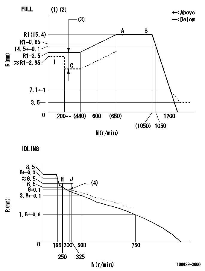
N:Pump speed
R:Rack position (mm)
(1)Torque cam stamping: T1
(2)Tolerance for racks not indicated: +-0.05mm.
(3)Boost compensator stroke: BCL
(4)Damper spring setting
----------
T1=AE56 BCL=2.4+-0.1mm
----------
----------
T1=AE56 BCL=2.4+-0.1mm
----------
Speed control lever angle
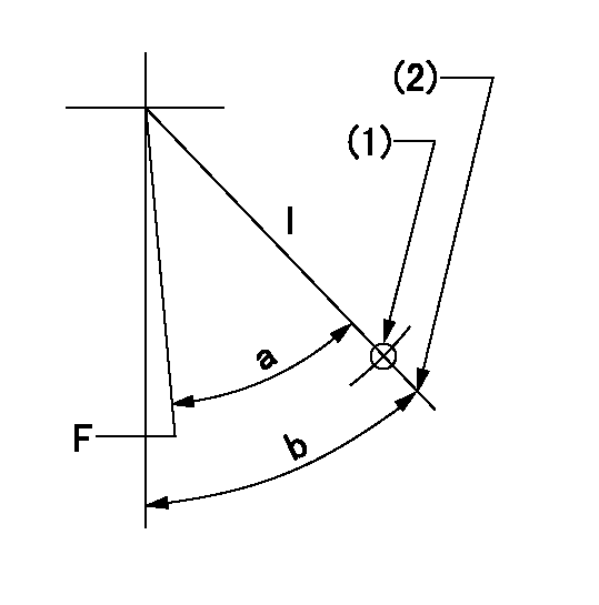
F:Full speed
I:Idle
(1)Use the hole at R = aa
(2)Stopper bolt set position 'H'
----------
aa=42.5mm
----------
a=36deg+-3deg b=36.5deg+-5deg
----------
aa=42.5mm
----------
a=36deg+-3deg b=36.5deg+-5deg
Stop lever angle
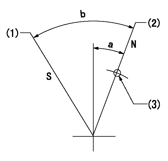
N:Pump normal
S:Stop the pump.
(1)At pump speed aa and rack position bb, set the stopper screw. (After setting, apply red paint.)
(2)Position at the normal side lever position (back off the stop screw and move fully to the normal side). Next, screw in the stop screw and set where it contacts the stop lever.
(3)Use the hole above R = cc
----------
aa=0r/min bb=0.5+-0.3mm cc=30mm
----------
a=20deg+-5deg b=45deg+-5deg
----------
aa=0r/min bb=0.5+-0.3mm cc=30mm
----------
a=20deg+-5deg b=45deg+-5deg
0000001301

(1)Pump vertical direction
(2)Coupling's key groove position at No 1 cylinder's beginning of injection
(3)Pre-stroke: aa
(4)-
----------
aa=6.4+-0.03mm
----------
a=(10deg)
----------
aa=6.4+-0.03mm
----------
a=(10deg)
0000001901

A:Sealing position
B:Pre-stroke actuator
1. When installing the pre-stroke actuator on the pump, first tighten the installation bolts loosely, then move the actuator fully counterclockwise (viewed from the drive side).
Temporary tightening torque: 1 - 1.5 N.m (0.1 - 0.15 kgf.m)
2. Move the actuator in the clockwise direction when viewed from the drive side, and adjust so that it becomes the adjustment point of the adjustment value. Then tighten it.
Tightening torque: 7^9 N.m (0.7^0.9 kgf.m)
3. After prestroke actuator installation adjustment, simultaneously stamp both the actuator side and housing side.
----------
----------
----------
----------
0000002201 RACK SENSOR
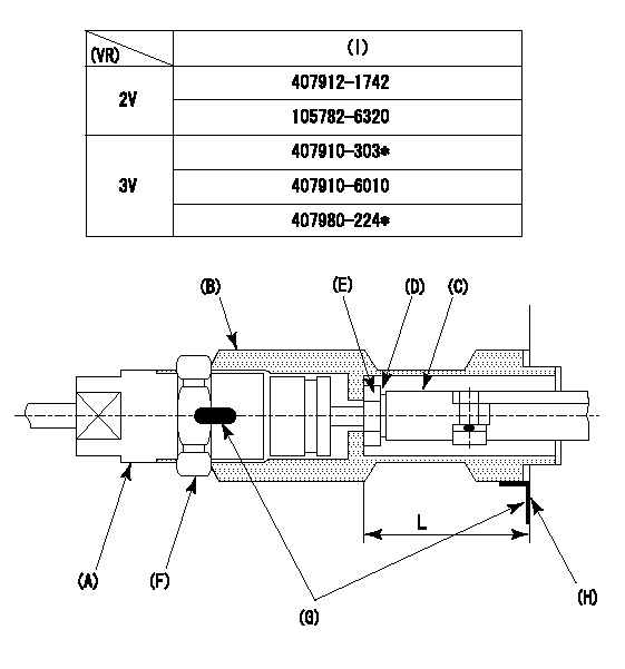
(VR) measurement voltage
(I) Part number of the control unit
(G) Apply red paint.
(H): End surface of the pump
Adjustment of the rack sensor (-2320)
1. Rack limit adjustment
(1)After mounting the joint (B), select the shim (D) so that the rack position is in the rack limit position.
(2)Install the rod (e) to the block (c).
(3)At the rack limit, set the distance between the pump end face and the rod (E) to L1.
2. Rack sensor
(1)Screw in the bobbin (A) until it contacts the joint (B).
(2)Fix the speed control lever at the full side and set the pump speed at N1.
(3)Adjust the depth that the bobbin (A) is screwed in so that the control unit's rack sensor output voltage is VR+-0.01 (V), then tighten the nut (F). (If equipped with a boost compensator, perform with boost pressure applied.)
(4)Adjust the bobbin (a) so that the rack sensor output voltage becomes VR +-0.01(V).
(5)Apply red paint to both the joint (b) and the nut (f) join, and the joint (b) and the pump join. Output voltage VR +-0.01(V), speed N1 r/min, rack position Ra mm
----------
L=43+-0.1mm N1=1000r/min Ra=R1(15.4)mm
----------
----------
L=43+-0.1mm N1=1000r/min Ra=R1(15.4)mm
----------
Information:
Action Required
See the attached procedure.
Service Claim Allowances
Group 1 Affected Product
All Group 2 Affected Product
This is a 1-hour job.
All Group 3 Affected Product
This is a .3-hour job. Submit a supplemental claim for Group 3 if a claim for Group 1 or 2 has already been submitted.
Parts Disposition
Handle the parts in accordance with your Warranty Bulletin on warranty parts handling.
Attach. (1-Rework Procedure)Rework Procedure
Refer to the following instructions and illustrations. Replace the existing fuel lines and their related parts with the new fuel line groups.
To insure correct clamp locations, install left and right fuel line groups as assembled. However, if clamps are removed, mark locations to insure correct positions when reassembling.
On the 992C Wheel Loader, it is necessary to remove the 6N8322 Air Outlet Tube Assembly to be able to install the right bank fuel line group.
Tighten the fuel line clamp screws to a torque of 2.25 N m (20 lb in). Do not over tighten. Use a 6V6069 Torque Screwdriver or similar tool to tighten the screws.
Group 1 Procedure
1. Clean and paint the new 6I0361 and 7E3539 Fuel Line Groups before proceeding to the job site.A) "Tape Off" the number 3, 5, and 6 fuel lines in the area of the tower clamp. (See Illustration 1 - Part 4 of 5, Section C-C)B) Install 5F2807 Plastic Caps and 2F2990 Plastic Plugs on the ends of the fuel lines.C) Clean and paint the fuel line groups.D) After drying completely, remove the tape. Do not remove the plastic caps and plugs until the fuel lines are ready to be installed on the engine. Transport the fuel line groups in their original boxes.2. Remove all mounting bolts from the fuel line brackets at the aftercooler housing. Except for the tower clamp assembly, new mounting bolts and washers will be used. Keep the washers. The washers may be needed later as spacers.3. A) Disassemble the tower clamp assembly behind the fuel injection pump. The 9Y3356 Clamp and 9Y3359 Clamp As. that form the tower clamp will be reused. (See Illustration 1 - Part 4 of 5, Section C-C)B) Disconnect the 2 line clamps from the 9Y3361 Bracket (Front V Bracket).C) Disconnect the 6 line clamps from the 7E5779 Bracket (Large V Bracket).4. Disconnect all the fuel lines at the fuel injection pump and at the adaptors in the valve cover bases.5. A) Remove the left and right side fuel line groups as separate assemblies.B) Remove the 9Y3361 Bracket (Front V Bracket). Replace it with a new 6I0347 Bracket.6. Remove the plastic caps and plugs from the fuel lines. Set the new 6I0361 Fuel Lines Group (left side) and the new 7E3539 Fuel Lines Group (right side) in place and hand tighten the fuel nuts. (See Illustration 1 - Part 1 of 5). If any of the ends of the individual fuel lines are not square with the bonnets in the fuel injection pump or with the adaptors in the valve cover bases, gently bend the lines by hand to align the