Information injection-pump assembly
BOSCH
F 01G 09U 0EP
f01g09u0ep
ZEXEL
108622-3364
1086223364
HINO
220008674A
220008674a

Rating:
Service parts 108622-3364 INJECTION-PUMP ASSEMBLY:
1.
_
5.
AUTOM. ADVANCE MECHANIS
9.
_
11.
Nozzle and Holder
23600-2412E
12.
Open Pre:MPa(Kqf/cm2)
16.7{170}/23.5{240}
14.
NOZZLE
Include in #1:
108622-3364
as INJECTION-PUMP ASSEMBLY
Cross reference number
BOSCH
F 01G 09U 0EP
f01g09u0ep
ZEXEL
108622-3364
1086223364
HINO
220008674A
220008674a
Zexel num
Bosch num
Firm num
Name
Calibration Data:
Adjustment conditions
Test oil
1404 Test oil ISO4113 or {SAEJ967d}
1404 Test oil ISO4113 or {SAEJ967d}
Test oil temperature
degC
40
40
45
Nozzle and nozzle holder
105780-8250
Bosch type code
1 688 901 101
Nozzle
105780-0120
Bosch type code
1 688 901 990
Nozzle holder
105780-2190
Opening pressure
MPa
20.7
Opening pressure
kgf/cm2
211
Injection pipe
Outer diameter - inner diameter - length (mm) mm 8-3-600
Outer diameter - inner diameter - length (mm) mm 8-3-600
Overflow valve
134424-1420
Overflow valve opening pressure
kPa
162
147
177
Overflow valve opening pressure
kgf/cm2
1.65
1.5
1.8
Tester oil delivery pressure
kPa
255
255
255
Tester oil delivery pressure
kgf/cm2
2.6
2.6
2.6
PS/ACT control unit part no.
407980-2
24*
Digi switch no.
31
Direction of rotation (viewed from drive side)
Left L
Left L
Injection timing adjustment
Direction of rotation (viewed from drive side)
Left L
Left L
Injection order
1-4-2-6-
3-5
Pre-stroke
mm
6.4
6.37
6.43
Beginning of injection position
Drive side NO.1
Drive side NO.1
Difference between angles 1
Cal 1-4 deg. 60 59.75 60.25
Cal 1-4 deg. 60 59.75 60.25
Difference between angles 2
Cyl.1-2 deg. 120 119.75 120.25
Cyl.1-2 deg. 120 119.75 120.25
Difference between angles 3
Cal 1-6 deg. 180 179.75 180.25
Cal 1-6 deg. 180 179.75 180.25
Difference between angles 4
Cal 1-3 deg. 240 239.75 240.25
Cal 1-3 deg. 240 239.75 240.25
Difference between angles 5
Cal 1-5 deg. 300 299.75 300.25
Cal 1-5 deg. 300 299.75 300.25
Injection quantity adjustment
Adjusting point
-
Rack position
15.4
Pump speed
r/min
550
550
550
Average injection quantity
mm3/st.
186.5
183.5
189.5
Max. variation between cylinders
%
0
-2
2
Basic
*
Fixing the rack
*
PS407980-224*
V
2.45+-0.
01
PS407980-224*
mm
4+-0.05
Standard for adjustment of the maximum variation between cylinders
*
Injection quantity adjustment_02
Adjusting point
H
Rack position
8.5+-0.5
Pump speed
r/min
250
250
250
Average injection quantity
mm3/st.
9
6
12
Max. variation between cylinders
%
0
-15
15
Fixing the rack
*
PS407980-224*
V
V1+0.05+
-0.01
PS407980-224*
mm
6.3+-0.0
3
Standard for adjustment of the maximum variation between cylinders
*
Remarks
Refer to items regarding the pre-stroke actuator
Refer to items regarding the pre-stroke actuator
Injection quantity adjustment_03
Adjusting point
A
Rack position
R1(15.4)
Pump speed
r/min
550
550
550
Average injection quantity
mm3/st.
186.5
184.5
188.5
Basic
*
Fixing the lever
*
Boost pressure
kPa
86
86
Boost pressure
mmHg
645
645
PS407980-224*
V
2.45+-0.
01
PS407980-224*
mm
4+-0.05
Injection quantity adjustment_04
Adjusting point
B
Rack position
(R1+0.15
)
Pump speed
r/min
1000
1000
1000
Average injection quantity
mm3/st.
192
186
198
Fixing the lever
*
Boost pressure
kPa
86
86
Boost pressure
mmHg
645
645
PS407980-224*
V
2.45+-0.
01
PS407980-224*
mm
4+-0.05
Injection quantity adjustment_05
Adjusting point
D
Rack position
-
Pump speed
r/min
100
100
100
Average injection quantity
mm3/st.
250
245
255
Fixing the lever
*
Boost pressure
kPa
86
86
Boost pressure
mmHg
645
645
Rack limit
*
PS407980-224*
V
2.45+-0.
01
PS407980-224*
mm
4+-0.05
Boost compensator adjustment
Pump speed
r/min
300
300
300
Rack position
R1-2.85
Boost pressure
kPa
10
10
12
Boost pressure
mmHg
75
75
90
Boost compensator adjustment_02
Pump speed
r/min
300
300
300
Rack position
R1(15.4)
Boost pressure
kPa
72.6
72.6
72.6
Boost pressure
mmHg
545
545
545
0000001601
Pre-stroke
mm
6.4
6.37
6.43
Remarks
When the timing sleeve is pushed up
When the timing sleeve is pushed up
_02
Connector angle
deg.
8.5
8
9
Remarks
When the eccentric pin is tightened
When the eccentric pin is tightened
_03
Supply voltage
V
24
23.5
24.5
Ambient temperature
degC
23
18
28
Pre-stroke
mm
4
3.95
4.05
Output voltage
V
2.45
2.44
2.46
Adjustment
*
_04
Supply voltage
V
24
23.5
24.5
Ambient temperature
degC
23
18
28
Pre-stroke
mm
6.4
6.37
6.43
Output voltage
V
1.2
1
1.4
Confirmation
*
Remarks
Output voltage V1
Output voltage V1
_05
Supply voltage
V
24
23.5
24.5
Ambient temperature
degC
23
18
28
Pre-stroke
mm
3.4
Output voltage
V
3
2.98
3
Confirmation
*
_06
Supply voltage
V
24
23.5
24.5
Ambient temperature
degC
23
18
28
Output voltage
V
3.05
3.05
Confirmation of operating range
*
Test data Ex:
Governor adjustment
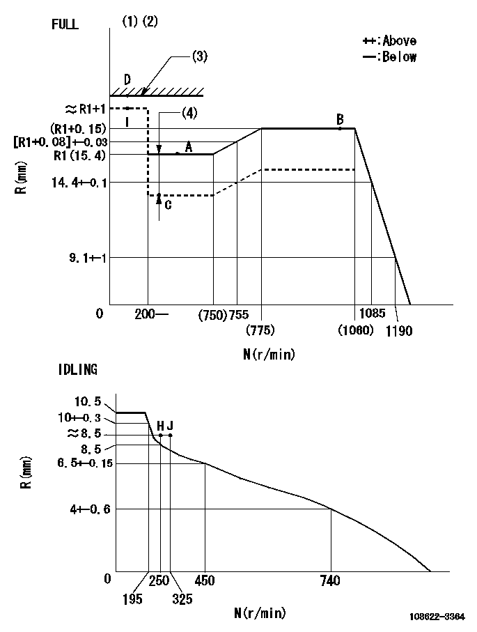
N:Pump speed
R:Rack position (mm)
(1)Torque cam stamping: T1
(2)Tolerance for racks not indicated: +-0.05mm.
(3)RACK LIMIT
(4)Boost compensator stroke: BCL
----------
T1=AC08 BCL=2.85+-0.1mm
----------
----------
T1=AC08 BCL=2.85+-0.1mm
----------
Speed control lever angle
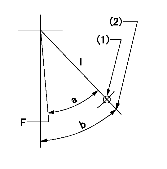
F:Full speed
I:Idle
(1)Use the hole at R = aa
(2)Stopper bolt setting
----------
aa=42.5mm
----------
a=(31deg)+-3deg b=36.5deg+-5deg
----------
aa=42.5mm
----------
a=(31deg)+-3deg b=36.5deg+-5deg
Stop lever angle
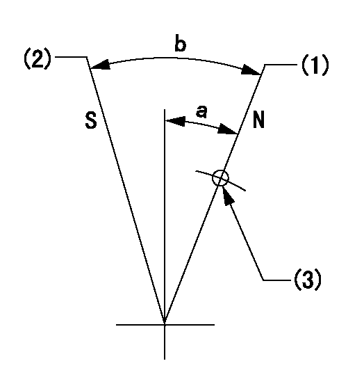
N:Pump normal
S:Stop the pump.
(1)Position at the normal side lever position (back off the stop screw and move fully to the normal side). Next, screw in the stop screw and set where it contacts the stop lever.
(2)At pump speed aa and rack position bb, set the stopper screw. (After setting, apply red paint.)
(3)Use the hole above R = cc
----------
aa=0r/min bb=1.5+-0.3mm cc=30mm
----------
a=20deg+-5deg b=45deg+-5deg
----------
aa=0r/min bb=1.5+-0.3mm cc=30mm
----------
a=20deg+-5deg b=45deg+-5deg
0000001301

(1)Pump vertical direction
(2)Coupling's key groove position at No 1 cylinder's beginning of injection
(3)Pre-stroke: aa
(4)-
----------
aa=6.4+-0.03mm
----------
a=(1deg)
----------
aa=6.4+-0.03mm
----------
a=(1deg)
0000001901

A:Sealing position
B:Pre-stroke actuator
1. When installing the pre-stroke actuator on the pump, first tighten the installation bolts loosely, then move the actuator fully counterclockwise (viewed from the drive side).
Temporary tightening torque: 1 - 1.5 N.m (0.1 - 0.15 kgf.m)
2. Move the actuator in the clockwise direction when viewed from the drive side, and adjust so that it becomes the adjustment point of the adjustment value. Then tighten it.
Tightening torque: 7^9 N.m (0.7^0.9 kgf.m)
3. After prestroke actuator installation adjustment, simultaneously stamp both the actuator side and housing side.
----------
----------
----------
----------
0000002201 RACK SENSOR
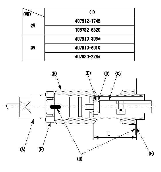
(VR) measurement voltage
(I) Part number of the control unit
(G) Apply red paint.
(H): End surface of the pump
Adjustment of the rack sensor (-2320)
1. Rack limit adjustment
(1)After mounting the joint (B), select the shim (D) so that the rack position is in the rack limit position.
(2)Install the rod (e) to the block (c).
(3)At the rack limit, set the distance between the pump end face and the rod (E) to L1.
2. Rack sensor
(1)Screw in the bobbin (A) until it contacts the joint (B).
(2)Fix the speed control lever at the full side and set the pump speed at N1.
(3)Adjust the depth that the bobbin (A) is screwed in so that the control unit's rack sensor output voltage is VR+-0.01 (V), then tighten the nut (F). (If equipped with a boost compensator, perform with boost pressure applied.)
(4)Adjust the bobbin (a) so that the rack sensor output voltage becomes VR +-0.01(V).
(5)Apply red paint to both the joint (b) and the nut (f) join, and the joint (b) and the pump join. Output voltage VR +-0.01(V), speed N1 r/min, rack position Ra mm
----------
L=43+-0.1mm N1=1000r/min Ra=(R1+0.15)mm
----------
----------
L=43+-0.1mm N1=1000r/min Ra=(R1+0.15)mm
----------
Information:
3T1888 Alternator 24V 50A (Delco-Remy Number 117248)
3T1888 Alternator1. Remove the covers from the end of the alternator to get access to the voltage regulator.
Delco-Remy Regulator Adjustment
(1) Potentiometer adjustment screw. (2) Transistor pins.2. Remove the rubber from the potentiometer so that the small screw can be seen.3. Connect a voltmeter across the batteries to measure the regulation of the voltage. The batteries must have a good charge for this measurement.4. Operate the alternator at medium speed for 30 seconds and take a measurement of the voltage. The voltage must be 27.5 1.0 volts. Turn the small screw counterclockwise to get less voltage output and clockwise to get more voltage output.5. After adjustment has been made, put a think layer of 3S6252 Silicone Rubber Sealant on the adjustment screw and install the covers. Make sure the location of the wires to the voltage regulator is not over the transistor pins. The transistor pins could make holes in the insulation for the wires and cause a short circuit.7N9720 Alternator 24V 35A (Bosch Number 0-122-469-001); 9G9538 Alternator 24V 50A (Bosch Number 0-122-469-002)
7N9720 AlternatorThe solid state regulator used with the Bosch Alternator is totally enclosed and non-adjustable. If the rate of charge is not correct a replacement of the regulator is necessary.9G4574 24V 35A (Nippondenso Number 100211-0860); 6T7223 24V 50A (Nippondenso Number 100211-0890)
9G4574 AlternatorNo adjustment can be made to change the rate of charge on the alternator regulator. If rate of charge is not correct, a replacement of the regulator is necessary.Starting System
Use the multimeter in the DCV range to find starting system components which do not function.Move the start control switch to activate the starter solenoid. Starter solenoid operation can be heard as the pinion of the starter motor is engaged with the ring gear on the engine flywheel.If the solenoid for the starter motor will not operate, it is possible that the current from the battery did not get to the solenoid. Fasten one lead of the multimeter to the connection (terminal) for the battery cable on the solenoid. Put the other lead to a good ground. A zero reading is an indication that there is a broken circuit from the battery. More testing is necessary when there is a voltage reading on the multimeter.The solenoid operation also closes the electric circuit to the motor. Connect one lead of the multimeter to the solenoid connection (terminal) that is fastened to the motor. Put the other lead to a good ground. Activate the starter solenoid and look at the multimeter. A reading of battery voltage shows the problem is in the motor. The motor must be removed for further testing. A zero reading on the multimeter shows that the solenoid contacts do not close. This is an indication of the need for repair to the solenoid or an adjustment to be made to the starter pinion clearance.Make a test with one multimeter lead fastened to the connection (terminal) for the small wire at the solenoid and the other lead to the