Information injection-pump assembly
BOSCH
F 01G 09U 0EN
f01g09u0en
ZEXEL
108622-3363
1086223363
HINO
220008673A
220008673a

Rating:
Service parts 108622-3363 INJECTION-PUMP ASSEMBLY:
1.
_
5.
AUTOM. ADVANCE MECHANIS
9.
_
11.
Nozzle and Holder
23600-2412E
12.
Open Pre:MPa(Kqf/cm2)
16.7{170}/23.5{240}
14.
NOZZLE
Include in #1:
108622-3363
as INJECTION-PUMP ASSEMBLY
Cross reference number
BOSCH
F 01G 09U 0EN
f01g09u0en
ZEXEL
108622-3363
1086223363
HINO
220008673A
220008673a
Zexel num
Bosch num
Firm num
Name
Calibration Data:
Adjustment conditions
Test oil
1404 Test oil ISO4113 or {SAEJ967d}
1404 Test oil ISO4113 or {SAEJ967d}
Test oil temperature
degC
40
40
45
Nozzle and nozzle holder
105780-8250
Bosch type code
1 688 901 101
Nozzle
105780-0120
Bosch type code
1 688 901 990
Nozzle holder
105780-2190
Opening pressure
MPa
20.7
Opening pressure
kgf/cm2
211
Injection pipe
Outer diameter - inner diameter - length (mm) mm 8-3-600
Outer diameter - inner diameter - length (mm) mm 8-3-600
Overflow valve
134424-1420
Overflow valve opening pressure
kPa
162
147
177
Overflow valve opening pressure
kgf/cm2
1.65
1.5
1.8
Tester oil delivery pressure
kPa
255
255
255
Tester oil delivery pressure
kgf/cm2
2.6
2.6
2.6
PS/ACT control unit part no.
407980-2
24*
Digi switch no.
31
Direction of rotation (viewed from drive side)
Left L
Left L
Injection timing adjustment
Direction of rotation (viewed from drive side)
Left L
Left L
Injection order
1-4-2-6-
3-5
Pre-stroke
mm
6.4
6.37
6.43
Beginning of injection position
Drive side NO.1
Drive side NO.1
Difference between angles 1
Cal 1-4 deg. 60 59.75 60.25
Cal 1-4 deg. 60 59.75 60.25
Difference between angles 2
Cyl.1-2 deg. 120 119.75 120.25
Cyl.1-2 deg. 120 119.75 120.25
Difference between angles 3
Cal 1-6 deg. 180 179.75 180.25
Cal 1-6 deg. 180 179.75 180.25
Difference between angles 4
Cal 1-3 deg. 240 239.75 240.25
Cal 1-3 deg. 240 239.75 240.25
Difference between angles 5
Cal 1-5 deg. 300 299.75 300.25
Cal 1-5 deg. 300 299.75 300.25
Injection quantity adjustment
Adjusting point
-
Rack position
15.4
Pump speed
r/min
550
550
550
Average injection quantity
mm3/st.
186.5
183.5
189.5
Max. variation between cylinders
%
0
-2
2
Basic
*
Fixing the rack
*
PS407980-224*
V
2.45+-0.
01
PS407980-224*
mm
4+-0.05
Standard for adjustment of the maximum variation between cylinders
*
Injection quantity adjustment_02
Adjusting point
H
Rack position
8.5+-0.5
Pump speed
r/min
250
250
250
Average injection quantity
mm3/st.
9
6
12
Max. variation between cylinders
%
0
-15
15
Fixing the rack
*
PS407980-224*
V
V1+0.05+
-0.01
PS407980-224*
mm
6.3+-0.0
3
Standard for adjustment of the maximum variation between cylinders
*
Remarks
Refer to items regarding the pre-stroke actuator
Refer to items regarding the pre-stroke actuator
Injection quantity adjustment_03
Adjusting point
A
Rack position
R1(15.4)
Pump speed
r/min
550
550
550
Average injection quantity
mm3/st.
186.5
184.5
188.5
Basic
*
Fixing the lever
*
Boost pressure
kPa
113
113
Boost pressure
mmHg
850
850
PS407980-224*
V
2.45+-0.
01
PS407980-224*
mm
4+-0.05
Injection quantity adjustment_04
Adjusting point
B
Rack position
(R1+0.15
)
Pump speed
r/min
1000
1000
1000
Average injection quantity
mm3/st.
192
186
198
Fixing the lever
*
Boost pressure
kPa
113
113
Boost pressure
mmHg
850
850
PS407980-224*
V
2.45+-0.
01
PS407980-224*
mm
4+-0.05
Injection quantity adjustment_05
Adjusting point
D
Rack position
-
Pump speed
r/min
100
100
100
Average injection quantity
mm3/st.
250
245
255
Fixing the lever
*
Boost pressure
kPa
113
113
Boost pressure
mmHg
850
850
Rack limit
*
PS407980-224*
V
2.45+-0.
01
PS407980-224*
mm
4+-0.05
Boost compensator adjustment
Pump speed
r/min
300
300
300
Rack position
R1-2.85
Boost pressure
kPa
37.3
37.3
39.3
Boost pressure
mmHg
280
280
295
Boost compensator adjustment_02
Pump speed
r/min
300
300
300
Rack position
R1(15.4)
Boost pressure
kPa
100
100
100
Boost pressure
mmHg
750
750
750
0000001601
Pre-stroke
mm
6.4
6.37
6.43
Remarks
When the timing sleeve is pushed up
When the timing sleeve is pushed up
_02
Connector angle
deg.
8.5
8
9
Remarks
When the eccentric pin is tightened
When the eccentric pin is tightened
_03
Supply voltage
V
24
23.5
24.5
Ambient temperature
degC
23
18
28
Pre-stroke
mm
4
3.95
4.05
Output voltage
V
2.45
2.44
2.46
Adjustment
*
_04
Supply voltage
V
24
23.5
24.5
Ambient temperature
degC
23
18
28
Pre-stroke
mm
6.4
6.37
6.43
Output voltage
V
1.2
1
1.4
Confirmation
*
Remarks
Output voltage V1
Output voltage V1
_05
Supply voltage
V
24
23.5
24.5
Ambient temperature
degC
23
18
28
Pre-stroke
mm
3.4
Output voltage
V
3
2.98
3
Confirmation
*
_06
Supply voltage
V
24
23.5
24.5
Ambient temperature
degC
23
18
28
Output voltage
V
3.05
3.05
Confirmation of operating range
*
Test data Ex:
Governor adjustment
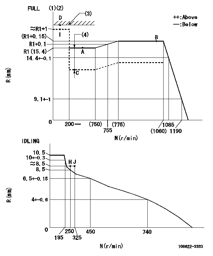
N:Pump speed
R:Rack position (mm)
(1)Torque cam stamping: T1
(2)Tolerance for racks not indicated: +-0.05mm.
(3)RACK LIMIT
(4)Boost compensator stroke: BCL
----------
T1=AC08 BCL=2.85+-0.1mm
----------
----------
T1=AC08 BCL=2.85+-0.1mm
----------
Speed control lever angle
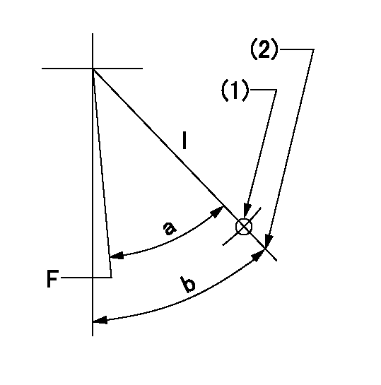
F:Full speed
I:Idle
(1)Use the hole at R = aa
(2)Stopper bolt set position 'H'
----------
aa=42.5mm
----------
a=(31deg)+-3deg b=36.5deg+-5deg
----------
aa=42.5mm
----------
a=(31deg)+-3deg b=36.5deg+-5deg
Stop lever angle
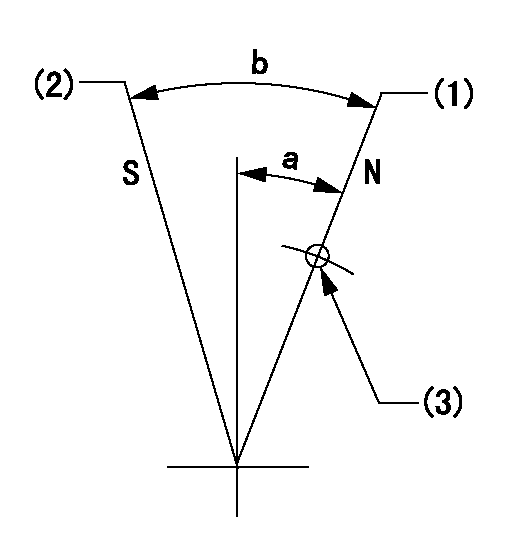
N:Pump normal
S:Stop the pump.
(1)Position at the normal side lever position (back off the stop screw and move fully to the normal side). Next, screw in the stop screw and set where it contacts the stop lever.
(2)Set the stopper bolt at speed = aa and rack position = bb (apply red paint after setting).
(3)Use the hole above R = cc
----------
aa=0r/min bb=1.5+-0.3mm cc=30mm
----------
a=20deg+-5deg b=45deg+-5deg
----------
aa=0r/min bb=1.5+-0.3mm cc=30mm
----------
a=20deg+-5deg b=45deg+-5deg
0000001301

(1)Pump vertical direction
(2)Coupling's key groove position at No 1 cylinder's beginning of injection
(3)Pre-stroke: aa
(4)-
----------
aa=6.4+-0.03mm
----------
a=(1deg)
----------
aa=6.4+-0.03mm
----------
a=(1deg)
0000001901

A:Sealing position
B:Pre-stroke actuator
1. When installing the pre-stroke actuator on the pump, first tighten the installation bolts loosely, then move the actuator fully counterclockwise (viewed from the drive side).
Temporary tightening torque: 1 - 1.5 N.m (0.1 - 0.15 kgf.m)
2. Move the actuator in the clockwise direction when viewed from the drive side, and adjust so that it becomes the adjustment point of the adjustment value. Then tighten it.
Tightening torque: 7^9 N.m (0.7^0.9 kgf.m)
3. After prestroke actuator installation adjustment, simultaneously stamp both the actuator side and housing side.
----------
----------
----------
----------
0000002201 RACK SENSOR
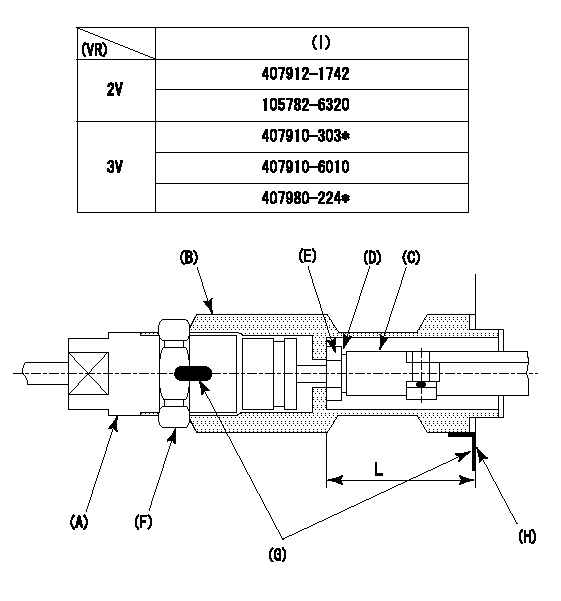
(VR) measurement voltage
(I) Part number of the control unit
(G) Apply red paint.
(H): End surface of the pump
Adjustment of the rack sensor (-2320)
1. Rack limit adjustment
(1)After mounting the joint (B), select the shim (D) so that the rack position is in the rack limit position.
(2)Install the rod (e) to the block (c).
(3)At the rack limit, set the distance between the pump end face and the rod (E) to L1.
2. Rack sensor
(1)Screw in the bobbin (A) until it contacts the joint (B).
(2)Fix the speed control lever at the full side and set the pump speed at N1.
(3)Adjust the depth that the bobbin (A) is screwed in so that the control unit's rack sensor output voltage is VR+-0.01 (V), then tighten the nut (F). (If equipped with a boost compensator, perform with boost pressure applied.)
(4)Adjust the bobbin (a) so that the rack sensor output voltage becomes VR +-0.01(V).
(5)Apply red paint to both the joint (b) and the nut (f) join, and the joint (b) and the pump join. Output voltage VR +-0.01(V), speed N1 r/min, rack position Ra mm
----------
L=43+-0.1mm N1=1000r/min Ra=(R1+0.15)mm
----------
----------
L=43+-0.1mm N1=1000r/min Ra=(R1+0.15)mm
----------
Information:
Delco-Remy Alternator
(1) Regulator. (2) Roller bearing. (3) Stator winding. (4) Ball bearing. (5) Rectifier bridge. (6) Field winding. (7) Rotor assembly. (8) Fan.Alternator (Bosch)
The alternator is driven by V-belts from the crankshaft pulley. This alternator is a three phase, self-rectifying charging unit. The regulator is part of the alternator.
Bosch Alternator
(1) Fan. (2) Stator winding. (3) Field winding. (4) Regulator. (5) Ball bearing. (6) Roller bearing. (7) Rotor. (8) Rectifier assembly.This alternator design has no need for slip rings or brushes, and the only part that has movement is the rotor assembly. All conductors that carry current are stationary. The conductors are: the field winding, stator windings, six rectifying diodes, and the regulator circuit components.The rotor assembly has many magnetic poles like fingers with air space between each opposite pole. The poles have residual magnetism (like permanent magnets) that produce a small amount of magnet-like lines of force (magnetic field) between the poles. As the rotor assembly begins to turn between the field winding and the stator windings, a small amount of alternating current (AC) is produced in the stator windings from the small magnetic lines of force made by the residual magnetism of the poles. This AC current is changed to direct current (DC) when it passes through the diodes of the rectifier bridge. Most of this current goes to charge the battery and to supply the low amperage circuit, and the remainder is sent to the field windings. The DC current flow through the field windings (wires around an iron core) now increases the strength of the magnetic lines of force. These stronger lines of force now increase the amount of AC current produced in the stator windings. The increased speed of the rotor assembly also increases the current and voltage output of the alternator.The voltage regulator is a solid state (transistor, stationary parts) electronic switch. It feels the voltage in the system and switches on and off many times a second to control the field current (DC current to the field windings) for the alternator to make the needed voltage output.Alternator (Nippondenso)
The alternator is driven by a V-belt from the crankshaft pulley. The only part in the alternator which has movement is rotor assembly (9). Rotor assembly (9) is held in position by a ball bearing at each end of rotor shaft (8).The alternator is made up of a frame (3) on the drive end, rotor assembly (9), stator assembly (5), rectifier assembly (11), brushes (7) and holder assembly, slip rings (13), rear end frame (12) and regulator (6). Drive pulley (1) has a fan (2) for heat removal by the movement of air through the alternator.
Alternator Schematic (With Regulator Attached)
(1) Pulley. (2) Fan. (3) Drive end frame. (4) Stator coils. (5) Stator assembly. (6) Regulator. (7) Brushes. (8) Rotor shaft. (9) Rotor assembly. (10) Field windings. (11) Rectifier assembly. (12) Rear end frame. (13) Slip rings.Rotor assembly (9) has field windings (10) (wires around an iron core) which make magnetic lines of force when direct