Information injection-pump assembly
BOSCH
F 01G 09U 0EB
f01g09u0eb
ZEXEL
108622-3183
1086223183
HINO
220008232A
220008232a

Rating:
Cross reference number
BOSCH
F 01G 09U 0EB
f01g09u0eb
ZEXEL
108622-3183
1086223183
HINO
220008232A
220008232a
Zexel num
Bosch num
Firm num
Name
Calibration Data:
Adjustment conditions
Test oil
1404 Test oil ISO4113 or {SAEJ967d}
1404 Test oil ISO4113 or {SAEJ967d}
Test oil temperature
degC
40
40
45
Nozzle and nozzle holder
105780-8140
Bosch type code
EF8511/9A
Nozzle
105780-0000
Bosch type code
DN12SD12T
Nozzle holder
105780-2080
Bosch type code
EF8511/9
Opening pressure
MPa
17.2
Opening pressure
kgf/cm2
175
Injection pipe
Outer diameter - inner diameter - length (mm) mm 8-3-600
Outer diameter - inner diameter - length (mm) mm 8-3-600
Overflow valve
134424-1520
Overflow valve opening pressure
kPa
162
147
177
Overflow valve opening pressure
kgf/cm2
1.65
1.5
1.8
Tester oil delivery pressure
kPa
157
157
157
Tester oil delivery pressure
kgf/cm2
1.6
1.6
1.6
PS/ACT control unit part no.
407980-2
24*
Digi switch no.
31
Direction of rotation (viewed from drive side)
Right R
Right R
Injection timing adjustment
Direction of rotation (viewed from drive side)
Right R
Right R
Injection order
1-4-2-6-
3-5
Pre-stroke
mm
6.4
6.37
6.43
Beginning of injection position
Drive side NO.1
Drive side NO.1
Difference between angles 1
Cal 1-4 deg. 60 59.75 60.25
Cal 1-4 deg. 60 59.75 60.25
Difference between angles 2
Cyl.1-2 deg. 120 119.75 120.25
Cyl.1-2 deg. 120 119.75 120.25
Difference between angles 3
Cal 1-6 deg. 180 179.75 180.25
Cal 1-6 deg. 180 179.75 180.25
Difference between angles 4
Cal 1-3 deg. 240 239.75 240.25
Cal 1-3 deg. 240 239.75 240.25
Difference between angles 5
Cal 1-5 deg. 300 299.75 300.25
Cal 1-5 deg. 300 299.75 300.25
Injection quantity adjustment
Adjusting point
A
Rack position
8.9
Pump speed
r/min
550
550
550
Average injection quantity
mm3/st.
151.7
149.7
153.7
Max. variation between cylinders
%
0
-2
2
Basic
*
Fixing the lever
*
Boost pressure
kPa
40.7
40.7
Boost pressure
mmHg
305
305
PS407980-224*
V
V1+0.05+
-0.01
PS407980-224*
mm
6.3+-0.0
3
Remarks
Refer to items regarding the pre-stroke actuator
Refer to items regarding the pre-stroke actuator
Injection quantity adjustment_02
Adjusting point
B
Rack position
9.35
Pump speed
r/min
1075
1075
1075
Average injection quantity
mm3/st.
153
150
156
Fixing the lever
*
Boost pressure
kPa
40.7
40.7
Boost pressure
mmHg
305
305
PS407980-224*
V
V1+0.05+
-0.01
PS407980-224*
mm
6.3+-0.0
3
Injection quantity adjustment_03
Adjusting point
C
Rack position
-
Pump speed
r/min
300
300
300
Average injection quantity
mm3/st.
194
189
199
Fixing the lever
*
Boost pressure
kPa
40.7
40.7
Boost pressure
mmHg
305
305
Rack limit
*
PS407980-224*
V
V1+0.05+
-0.01
PS407980-224*
mm
6.3+-0.0
3
Injection quantity adjustment_04
Adjusting point
D
Rack position
4+-0.5
Pump speed
r/min
225
225
225
Average injection quantity
mm3/st.
12.5
9.5
15.5
Max. variation between cylinders
%
0
-15
15
Fixing the rack
*
Boost pressure
kPa
0
0
0
Boost pressure
mmHg
0
0
0
PS407980-224*
V
V1+0.05+
-0.01
PS407980-224*
mm
6.3+-0.0
3
Injection quantity adjustment_05
Adjusting point
E
Rack position
7.8
Pump speed
r/min
400
400
400
Average injection quantity
mm3/st.
132.2
129.2
135.2
Fixing the lever
*
Boost pressure
kPa
0
0
0
Boost pressure
mmHg
0
0
0
PS407980-224*
V
V1+0.05+
-0.01
PS407980-224*
mm
6.3+-0.0
3
Injection quantity adjustment_06
Adjusting point
F
Rack position
-
Pump speed
r/min
100
100
100
Average injection quantity
mm3/st.
134
134
Fixing the lever
*
Boost pressure
kPa
0
0
0
Boost pressure
mmHg
0
0
0
PS407980-224*
V
V1+0.05+
-0.01
PS407980-224*
mm
6.3+-0.0
3
Injection quantity adjustment_07
Adjusting point
G
Rack position
9.1
Pump speed
r/min
850
850
850
Average injection quantity
mm3/st.
150.8
147.8
153.8
Fixing the lever
*
Boost pressure
kPa
40.7
40.7
Boost pressure
mmHg
305
305
PS407980-224*
V
V1+0.05+
-0.01
PS407980-224*
mm
6.3+-0.0
3
Boost compensator adjustment
Pump speed
r/min
550
550
550
Rack position
7.8
Boost pressure
kPa
9.3
7.3
9.3
Boost pressure
mmHg
70
55
70
Boost compensator adjustment_02
Pump speed
r/min
550
550
550
Rack position
8.9
Boost pressure
kPa
27.3
27.3
27.3
Boost pressure
mmHg
205
205
205
0000001601
Pre-stroke
mm
6.4
6.37
6.43
Remarks
When the timing sleeve is pushed up
When the timing sleeve is pushed up
_02
Connector angle
deg.
5
4.5
5.5
Remarks
When the eccentric pin is tightened
When the eccentric pin is tightened
_03
Supply voltage
V
24
23.5
24.5
Ambient temperature
degC
23
18
28
Pre-stroke
mm
4
3.95
4.05
Output voltage
V
2.62
2.61
2.63
Adjustment
*
_04
Supply voltage
V
24
23.5
24.5
Ambient temperature
degC
23
18
28
Pre-stroke
mm
6.4
6.37
6.43
Output voltage
V
1.2
1
1.4
Confirmation
*
Remarks
Output voltage V1
Output voltage V1
_05
Supply voltage
V
24
23.5
24.5
Ambient temperature
degC
23
18
28
Pre-stroke
mm
3.4
Output voltage
V
3
2.98
3
Confirmation
*
_06
Supply voltage
V
24
23.5
24.5
Ambient temperature
degC
23
18
28
Output voltage
V
3.05
3.05
Confirmation of operating range
*
Test data Ex:
Governor adjustment
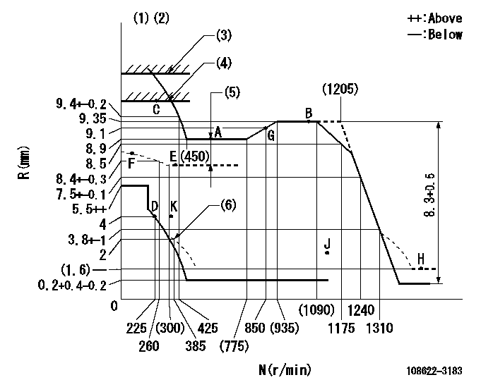
N:Pump speed
R:Rack position (mm)
(1)Tolerance for racks not indicated: +-0.05mm.
(2)Set idle at point K (N = N1, R = R1) and confirm that the injection quantity does not exceed Q1 at point J (N = N2).
(3)Stop lever setting: R2
(4)RACK LIMIT
(5)Boost compensator stroke: BCL
(6)Damper spring setting
----------
N1=325r/min R1=4mm N2=1100r/min Q1=3mm3/st R2=12.4+0.2mm BCL=1.1+-0.1mm
----------
----------
N1=325r/min R1=4mm N2=1100r/min Q1=3mm3/st R2=12.4+0.2mm BCL=1.1+-0.1mm
----------
Speed control lever angle

F:Full speed
----------
----------
a=12deg+-5deg
----------
----------
a=12deg+-5deg
0000000901

F:Full load
I:Idle
(1)Use the hole at R = aa
(2)Stopper bolt setting
----------
aa=91mm
----------
a=32deg+-3deg b=34.5+-5deg
----------
aa=91mm
----------
a=32deg+-3deg b=34.5+-5deg
Stop lever angle
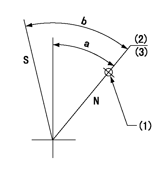
N:Pump normal
S:Stop the pump.
(1)Use the hole at R = aa
(2)Set the rack position at bb before adjusting the governor
(3)Set the stopper screw. (After setting, apply paint.)
----------
aa=33mm bb=12.4+0.2mm
----------
a=30deg+-5deg b=42deg+-5deg
----------
aa=33mm bb=12.4+0.2mm
----------
a=30deg+-5deg b=42deg+-5deg
0000001301

(1)Pump vertical direction
(2)Coupling's key groove position at No 1 cylinder's beginning of injection
(3)Pre-stroke: aa
(4)-
----------
aa=6.4+-0.03mm
----------
a=(40deg)
----------
aa=6.4+-0.03mm
----------
a=(40deg)
0000001901

(A): Pre-stroke actuator
(B): Stamp housings A and B at the same time.
(C): Stamping range
1. When installing the pre-stroke actuator on the pump, first tighten the installation bolts loosely, then move the actuator fully clockwise (viewed from the drive side).
Temporary tightening torque: 1 - 1.5 N.m (0.1 - 0.15 kgf.m)
2. Move the actuator in the counterclockwise direction when viewed from the drive side, and adjust so that it becomes the adjustment point of the adjustment value. Then tighten it.
Tightening torque: 7^9 N.m (0.7^0.9 kgf.m)
3. After prestroke actuator installation adjustment, simultaneously stamp both the actuator side and housing side.
----------
----------
----------
----------
0000002201 RACK SENSOR
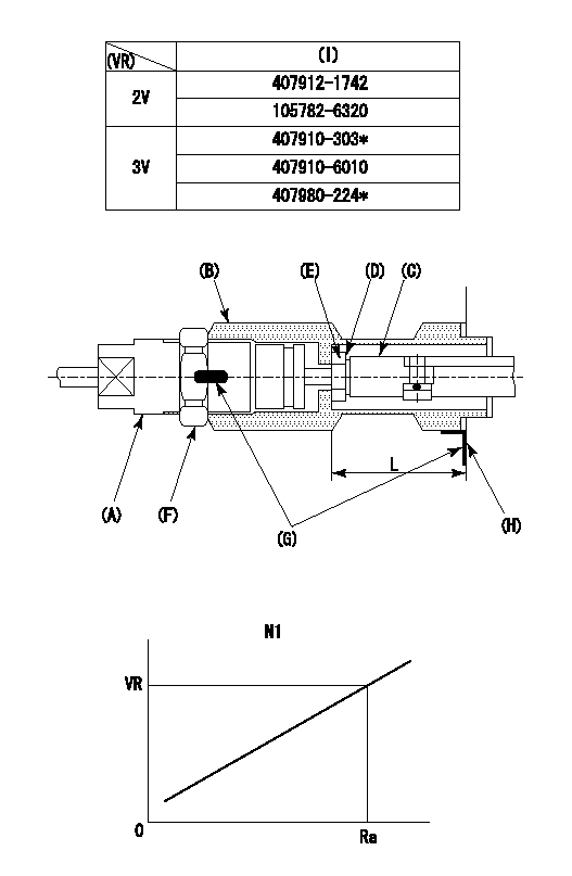
(VR) measurement voltage
(I) Part number of the control unit
(G) Apply red paint.
(H): End surface of the pump
Adjustment of the rack sensor (-0720)
1. Rack limit adjustment
(1)After mounting the joint (B), select the shim (D) so that the rack position is in the rack limit position.
(2)Install the rod (E) to the block (C).
(3)At the rack limit, set the distance between the pump end face and the rod (E) to L1.
2. Rack sensor
(1)Screw in the bobbin (A) until it contacts the joint (B).
(2)Fix the speed control lever at the full side and set the pump speed at N1.
(3)Adjust the depth that the bobbin (A) is screwed in so that the control unit's rack sensor output voltage is VR+-0.01 (V), then tighten the nut (F). (If equipped with a boost compensator, perform with boost pressure applied.)
(4)Apply red paint to both the joint (B) and the nut (F) join, and the joint (B) and the pump join. Output voltage VR +-0.01(V), speed N1, rack position Ra, rack sensor supply voltage 5+-0.01 (V)
----------
L=33.5+-0.1mm N1=550r/min Ra=8.9mm
----------
----------
L=33.5+-0.1mm N1=550r/min Ra=8.9mm
----------
0000002301 GOVERNOR TORQUE CONTROL

Dr:Torque control stroke
(A): Without torque control spring capsule
1. Adjustment procedures
(1)Procedure is the same as that for the RFD (former type), except that the positive torque control stroke must be determined at the full lever setting.
2. Procedures for adjustment
(1)Remove the torque control spring capsule.
(2)Operate the pump at approximately N1. (End of idling spring operation < N1.)
(3)Tilt the lever to the full side.
(4)Set so that R = RF.
(5)Increase the speed by pushing in the screw (attached to the bracket on the rear of the tension lever) through the adjusting window.
(6)Adjust so that the torque control stroke Dr1 can be obtained.
(7)Align N2 and N3 with the torque control spring capsule.
3. Final confirmation
(1)After final confirmation, temporarily set the load lever to N = N1, R = idling position.
(2)From this condition, increase speed to N = N4.
(3)Confirm that positive torque control stroke is Dr2.
----------
N1=500r/min N2=(775)r/min N3=(935)r/min N4=1100r/min RF=8.9mm Dr1=0.45mm Dr2=0+0.3mm
----------
----------
N1=500r/min N2=(775)r/min N3=(935)r/min N4=1100r/min RF=8.9mm Dr1=0.45mm Dr2=0+0.3mm
----------
Information:
Core Management
Please refer to the Caterpillar® Core Management Information System (CMIS 2) Parts Information application describing all reman part/CAF and related information. Also refer to other CMIS 2 inquiry applications such as Customer Profiles, Inspection Reason Codes, Inspection Line Inquiry, Add Charge Information, Entitlement Activity, Entitlement Inquiry, CCR Inquiry, CCR Entry, Shipment Processing; Process Packaging Grief; and Reporting to properly manage core returns and monitor inspection performance. This information will be available to all dealers worldwide after your CMIS 2 conversion date. In the meantime, please continue to use the current CMIS Entitlement Parts Inquiry Screen describing the list of parts in a Core Acceptability Family (CAF) and related part number detail.
For the latest updates of Reman Policies and Core Management (SELD0122), Core Management Systems & Operations Procedures (SELD0040), and Shipping Instructions (SELD0039), go to the Reman Dealer website https://reman.cat.com
If you have any questions regarding core return processing, feel free to call Corinth toll free at (800) 537-2928. For assistance with technical questions, call the Peoria Reman Customer Satisfaction Hot Line also toll free at (888) 88-REMAN or use our E-mail address--Reman_Help.
RWSmith
Remanufactured Products Group
LC-2148 (309) 675-5445