Information injection-pump assembly
ZEXEL
108622-3150
1086223150
HINO
220008050A
220008050a
Rating:
Cross reference number
ZEXEL
108622-3150
1086223150
HINO
220008050A
220008050a
Zexel num
Bosch num
Firm num
Name
Calibration Data:
Adjustment conditions
Test oil
1404 Test oil ISO4113 or {SAEJ967d}
1404 Test oil ISO4113 or {SAEJ967d}
Test oil temperature
degC
40
40
45
Nozzle and nozzle holder
105780-8140
Bosch type code
EF8511/9A
Nozzle
105780-0000
Bosch type code
DN12SD12T
Nozzle holder
105780-2080
Bosch type code
EF8511/9
Opening pressure
MPa
17.2
Opening pressure
kgf/cm2
175
Injection pipe
Outer diameter - inner diameter - length (mm) mm 8-3-600
Outer diameter - inner diameter - length (mm) mm 8-3-600
Overflow valve
134424-1520
Overflow valve opening pressure
kPa
162
147
177
Overflow valve opening pressure
kgf/cm2
1.65
1.5
1.8
Tester oil delivery pressure
kPa
157
157
157
Tester oil delivery pressure
kgf/cm2
1.6
1.6
1.6
PS/ACT control unit part no.
407980-2
24*
Digi switch no.
21
Direction of rotation (viewed from drive side)
Left L
Left L
Injection timing adjustment
Direction of rotation (viewed from drive side)
Left L
Left L
Injection order
1-4-2-6-
3-5
Pre-stroke
mm
6.4
6.37
6.43
Beginning of injection position
Drive side NO.1
Drive side NO.1
Difference between angles 1
Cal 1-4 deg. 60 59.75 60.25
Cal 1-4 deg. 60 59.75 60.25
Difference between angles 2
Cyl.1-2 deg. 120 119.75 120.25
Cyl.1-2 deg. 120 119.75 120.25
Difference between angles 3
Cal 1-6 deg. 180 179.75 180.25
Cal 1-6 deg. 180 179.75 180.25
Difference between angles 4
Cal 1-3 deg. 240 239.75 240.25
Cal 1-3 deg. 240 239.75 240.25
Difference between angles 5
Cal 1-5 deg. 300 299.75 300.25
Cal 1-5 deg. 300 299.75 300.25
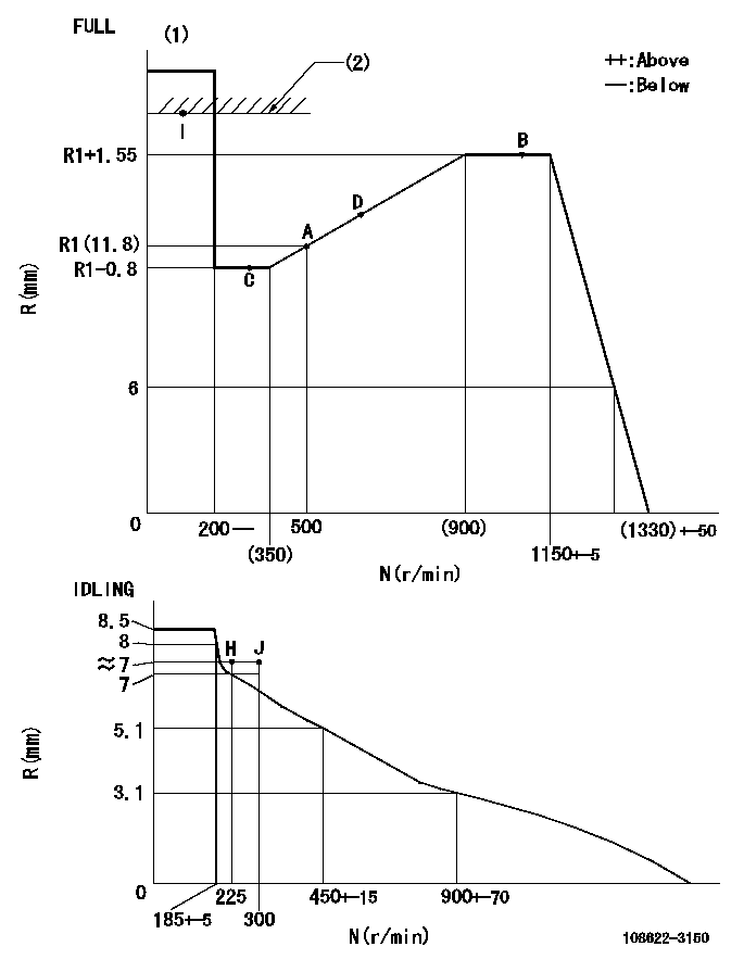
Injection quantity adjustment
Adjusting point
-
Rack position
11.8
Pump speed
r/min
500
500
500
Average injection quantity
mm3/st.
142.5
138.5
146.5
Max. variation between cylinders
%
0
-2
2
Basic
*
Fixing the rack
*
PS407980-224*
V
V1+0.05+
-0.01
PS407980-224*
mm
6.3+-0.0
3
Standard for adjustment of the maximum variation between cylinders
*
Remarks
Refer to items regarding the pre-stroke actuator
Refer to items regarding the pre-stroke actuator
Injection quantity adjustment_02
Adjusting point
H
Rack position
7+-0.5
Pump speed
r/min
225
225
225
Average injection quantity
mm3/st.
9.4
6.4
12.4
Max. variation between cylinders
%
0
-15
15
Fixing the rack
*
PS407980-224*
V
V1+0.05+
-0.01
PS407980-224*
mm
6.3+-0.0
3
Standard for adjustment of the maximum variation between cylinders
*
Injection quantity adjustment_03
Adjusting point
A
Rack position
R1(11.8)
Pump speed
r/min
500
500
500
Average injection quantity
mm3/st.
142.5
140.5
144.5
Basic
*
Fixing the lever
*
PS407980-224*
V
V1+0.05+
-0.01
PS407980-224*
mm
6.3+-0.0
3
Injection quantity adjustment_04
Adjusting point
B
Rack position
R1+1.55
Pump speed
r/min
1075
1075
1075
Average injection quantity
mm3/st.
167.8
161.8
173.8
Fixing the lever
*
PS407980-224*
V
V1+0.05+
-0.01
PS407980-224*
mm
6.3+-0.0
3
Injection quantity adjustment_05
Adjusting point
C
Rack position
R1-0.8
Pump speed
r/min
300
300
300
Average injection quantity
mm3/st.
105.6
99.6
111.6
Fixing the lever
*
PS407980-224*
V
V1+0.05+
-0.01
PS407980-224*
mm
6.3+-0.0
3
Injection quantity adjustment_06
Adjusting point
D
Rack position
(R1+0.7)
Pump speed
r/min
700
700
700
Average injection quantity
mm3/st.
151.8
145.8
157.8
Fixing the lever
*
PS407980-224*
V
V1+0.05+
-0.01
PS407980-224*
mm
6.3+-0.0
3
Injection quantity adjustment_07
Adjusting point
I
Rack position
-
Pump speed
r/min
100
100
100
Average injection quantity
mm3/st.
183
183
203
Fixing the lever
*
Rack limit
*
PS407980-224*
V
V1+0.05+
-0.01
PS407980-224*
mm
6.3+-0.0
3
0000001601
Pre-stroke
mm
6.4
6.37
6.43
Remarks
When the timing sleeve is pushed up
When the timing sleeve is pushed up
_02
Connector angle
deg.
5
4.5
5.5
Remarks
When the eccentric pin is tightened
When the eccentric pin is tightened
_03
Supply voltage
V
24
23.5
24.5
Ambient temperature
degC
23
18
28
Pre-stroke
mm
4
3.95
4.05
Output voltage
V
2.62
2.61
2.63
Adjustment
*
_04
Supply voltage
V
24
23.5
24.5
Ambient temperature
degC
23
18
28
Pre-stroke
mm
6.4
6.37
6.43
Output voltage
V
1.2
1
1.4
Confirmation
*
Remarks
Output voltage V1
Output voltage V1
_05
Supply voltage
V
24
23.5
24.5
Ambient temperature
degC
23
18
28
Pre-stroke
mm
3.4
Output voltage
V
3
2.98
3
Confirmation
*
_06
Supply voltage
V
24
23.5
24.5
Ambient temperature
degC
23
18
28
Output voltage
V
3.05
3.05
Confirmation of operating range
*
Test data Ex:
Governor adjustment
N:Pump speed
R:Rack position (mm)
(1)Torque cam stamping: T1
(2)RACK LIMIT
----------
T1=H38
----------
----------
T1=H38
----------
Speed control lever angle
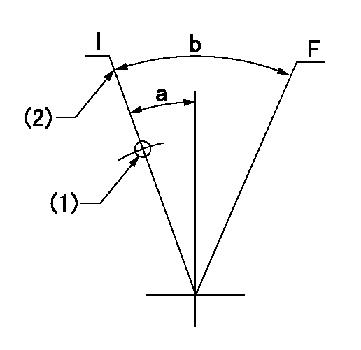
F:Full speed
I:Idle
(1)Use the hole at R = aa
(2)Stopper bolt setting
----------
aa=47mm
----------
a=18.5deg+-5deg b=(42deg)+-3deg
----------
aa=47mm
----------
a=18.5deg+-5deg b=(42deg)+-3deg
Stop lever angle
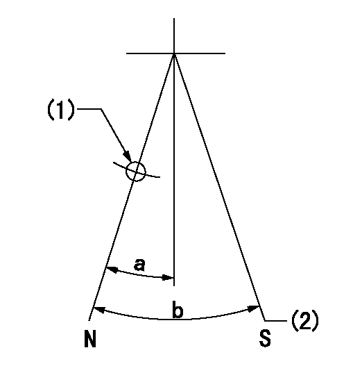
N:Pump normal
S:Stop the pump.
(1)Use the pin at R = aa
(2)With the speed lever in the full position at speed = bb, set the stopper screw so that the rack position = cc. After adjustment, apply red paint.
----------
aa=40mm bb=1150r/min cc=4.3-0.5mm
----------
a=31deg+-5deg b=37deg+-5deg
----------
aa=40mm bb=1150r/min cc=4.3-0.5mm
----------
a=31deg+-5deg b=37deg+-5deg
0000001301

(1)Pump vertical direction
(2)Coupling's key groove position at No 1 cylinder's beginning of injection
(3)Pre-stroke: aa
(4)-
----------
aa=6.4+-0.03mm
----------
a=(0deg)
----------
aa=6.4+-0.03mm
----------
a=(0deg)
0000001901

(A): Pre-stroke actuator
(B): Stamp housings A and B at the same time.
(C): Stamping range
1. When installing the pre-stroke actuator on the pump, first tighten the installation bolts loosely, then move the actuator fully clockwise (viewed from the drive side).
Temporary tightening torque: 1 - 1.5 N.m (0.1 - 0.15 kgf.m)
2. Move the actuator in the counterclockwise direction when viewed from the drive side, and adjust so that it becomes the adjustment point of the adjustment value. Then tighten it.
Tightening torque: 7^9 N.m (0.7^0.9 kgf.m)
3. After prestroke actuator installation adjustment, simultaneously stamp both the actuator side and housing side.
----------
----------
----------
----------
0000002201 RACK SENSOR

(VR) measurement voltage
(I) Part number of the control unit
(G) Apply red paint.
(H): End surface of the pump
1. Rack limit adjustment
(1)Mount the joint (B).
(2)Select the shim (D) so that the rack limit's rack position is obtained at that time.
(3)Install the rod (E) to the block (C).
The distance between the pump end face and the rod (E) at rack limit must be L.
2. Rack sensor adjustment (-0020)
(1)Screw in the bobbin (A) until it contacts the joint (B).
(2)Fix the speed control lever at the full side.
(3)Set at speed N.
(4)Adjust the depth that the bobbin (A) is screwed in so that the control unit's rack sensor output voltage is VR+-0.01 (V), then tighten the nut (F). (If equipped with a boost compensator, perform with boost pressure applied.)
(5)Adjust the bobbin (A) so that the rack sensor's output voltage is VR+-0.01.
(6)Apply G at two places.
Connecting part between the joint (B) and the nut (F)
Connecting part between the joint (B) and the end surface of the pump (H)
----------
L=38-0.2mm N=1075r/min Ra=R1(11.8)+1.55mm
----------
----------
L=38-0.2mm N=1075r/min Ra=R1(11.8)+1.55mm
----------
Information:
Fuel Injection Nozzles
Disassembly of Fuel Injection Nozzles
Inspection of Fuel Injection Nozzles
Check each fuel injection nozzle for the following, and if defects are found, repair or replace the fuel injection nozzle.(1) Inspection of injection start pressure(a) Install each fuel injection nozzle on the nozzle tester, and move the handle up and down to release air.(b) Operate the handle of the tester at a rate of about 1 stroke per second, and read the indication on the pressure gage. The indication rises slowly, and the indicator oscillates during spraying. To obtain the injection start pressure value, read the indication when the indicator starts to oscillate.
Inspection of fuel injection nozzle valve opening(c) If the injection start pressure deviates significantly from the standard value, disassemble the fuel injection nozzle, and make an adjustment by changing the washer thickness. 0.1 mm [0.0039 in.] thickness of shims will change the injection pressure 0.98 Mpa (10 kgf/cm2 [142 psi]. The shims are available in 10 different thickness from 1.25 to 1.70 mm [0.0492 to 0.0669 in.] increment of 0.05 mm [0.0020 in.]
Never tap the tip of the nozzle tip when removing the nozzle tip.
Replacement of fuel injection nozzle tip(2) Inspection of fuel injection nozzle spray pattern(a) When inspecting each fuel injection nozzle with the nozzle tester, also check the nozzle for clogs, spray pattern and leakage.(b) Make sure that the fuel is sprayed straight from the nozzle when the handle of the tester is operated at a rate of about 1 stroke per second.
Inspection of spray pattern of fuel injection nozzle(3) Cleaning and replacement of faulty nozzles(a) Loosen the nozzle retaining nut, remove the nozzle tip, and clean the needle valve and body.
Never tap the tip of the nozzle tip when removing the nozzle tip.
(b) Use a fresh cleaning solution to clean the needle valve and body. After cleaning, assemble the needle valve and body in clean diesel fuel. The needle valve and body are precision finished. Handle them carefully, and do not change the combination of parts.
Cleaning of fuel injection nozzle tip(c) Tighten the nozzle retaining nut on the nozzle tip to the specified torque.(d) If the spray pattern is still not acceptable after adjustment and cleaning, replace the nozzle tip. (a) Never touch the sliding surface of the needle valve.(b) When installing a new nozzle tip, remove the seal film (synthetic resin film), and slide needle valve in the nozzle in a fresh cleaning solution to remove anti-rust oil coating thoroughly from the new nozzleReassembly of Fuel Injection Nozzles
Fuel Filter
Disassembly and Inspection of Fuel Filter