Information injection-pump assembly
BOSCH
F 01G 09U 1C5
f01g09u1c5
ZEXEL
108622-2402
1086222402
MITSUBISHI
ME355478
me355478
Rating:
Service parts 108622-2402 INJECTION-PUMP ASSEMBLY:
1.
_
3.
GOVERNOR
5.
AUTOM. ADVANCE MECHANIS
7.
COUPLING PLATE
11.
Nozzle and Holder
12.
Open Pre:MPa(Kqf/cm2)
23.8(243)
15.
NOZZLE SET
Include in #1:
108622-2402
as INJECTION-PUMP ASSEMBLY
Cross reference number
BOSCH
F 01G 09U 1C5
f01g09u1c5
ZEXEL
108622-2402
1086222402
MITSUBISHI
ME355478
me355478
Zexel num
Bosch num
Firm num
Name
108622-2402
F 01G 09U 1C5
ME355478 MITSUBISHI
INJECTION-PUMP ASSEMBLY
6D24T2 K
6D24T2 K
Calibration Data:
Adjustment conditions
Test oil
1404 Test oil ISO4113 or {SAEJ967d}
1404 Test oil ISO4113 or {SAEJ967d}
Test oil temperature
degC
40
40
45
Nozzle and nozzle holder
105780-8250
Bosch type code
1 688 901 101
Nozzle
105780-0120
Bosch type code
1 688 901 990
Nozzle holder
105780-2190
Opening pressure
MPa
20.7
Opening pressure
kgf/cm2
211
Injection pipe
Outer diameter - inner diameter - length (mm) mm 8-3-600
Outer diameter - inner diameter - length (mm) mm 8-3-600
Overflow valve
131424-8020
Overflow valve opening pressure
kPa
255
221
289
Overflow valve opening pressure
kgf/cm2
2.6
2.25
2.95
Tester oil delivery pressure
kPa
255
255
255
Tester oil delivery pressure
kgf/cm2
2.6
2.6
2.6
RED3 control unit part number
407910-3
960
RED3 rack sensor specifications
mm
19
PS/ACT control unit part no.
407980-2
24*
Digi switch no.
31
Direction of rotation (viewed from drive side)
Right R
Right R
Injection timing adjustment
Direction of rotation (viewed from drive side)
Right R
Right R
Injection order
1-5-3-6-
2-4
Pre-stroke
mm
8.5
8.47
8.53
Beginning of injection position
Governor side NO.1
Governor side NO.1
Difference between angles 1
Cal 1-5 deg. 60 59.75 60.25
Cal 1-5 deg. 60 59.75 60.25
Difference between angles 2
Cal 1-3 deg. 120 119.75 120.25
Cal 1-3 deg. 120 119.75 120.25
Difference between angles 3
Cal 1-6 deg. 180 179.75 180.25
Cal 1-6 deg. 180 179.75 180.25
Difference between angles 4
Cyl.1-2 deg. 240 239.75 240.25
Cyl.1-2 deg. 240 239.75 240.25
Difference between angles 5
Cal 1-4 deg. 300 299.75 300.25
Cal 1-4 deg. 300 299.75 300.25
Injection quantity adjustment
Rack position
(13.5)
Vist
V
1.82
1.82
1.82
Pump speed
r/min
700
700
700
Average injection quantity
mm3/st.
191
189
193
Max. variation between cylinders
%
0
-2
2
Basic
*
PS407980-224*
V
2.45+-0.
01
PS407980-224*
mm
6.1+-0.0
5
Injection quantity adjustment_02
Rack position
(7)
Vist
V
2.8
2.7
2.9
Pump speed
r/min
270
270
270
Average injection quantity
mm3/st.
20
18
22
Max. variation between cylinders
%
0
-15
15
PS407980-224*
V
V1+0.05+
-0.01
PS407980-224*
mm
8.4+-0.0
3
Remarks
Refer to items regarding the pre-stroke actuator
Refer to items regarding the pre-stroke actuator
0000001201
Pre-stroke
mm
8.5
8.47
8.53
Remarks
When the timing sleeve is pushed up
When the timing sleeve is pushed up
_02
Connector angle
deg.
8.5
8
9
Remarks
When the eccentric pin is tightened
When the eccentric pin is tightened
_03
Supply voltage
V
24
23.5
24.5
Ambient temperature
degC
23
18
28
Pre-stroke
mm
6.1
6.05
6.15
Output voltage
V
2.45
2.44
2.46
Adjustment
*
_04
Supply voltage
V
24
23.5
24.5
Ambient temperature
degC
23
18
28
Pre-stroke
mm
8.5
8.47
8.53
Output voltage
V
1.2
1
1.4
Confirmation
*
Remarks
Output voltage V1
Output voltage V1
_05
Supply voltage
V
24
23.5
24.5
Ambient temperature
degC
23
18
28
Pre-stroke
mm
5.5
Output voltage
V
3
2.98
3
Confirmation
*
_06
Supply voltage
V
24
23.5
24.5
Ambient temperature
degC
23
18
28
Output voltage
V
3.05
3.05
Confirmation of operating range
*
Test data Ex:
Speed control lever angle
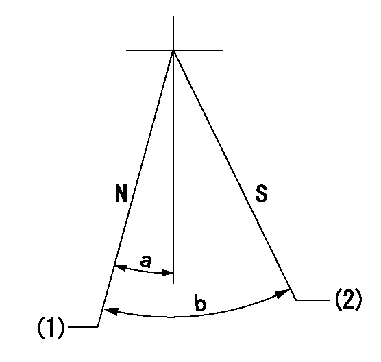
N:Pump normal
S:Stop the pump.
(1)Rack position = aa
(2)Rack position bb
----------
aa=20mm bb=1mm
----------
a=3deg+-5deg b=37deg+-5deg
----------
aa=20mm bb=1mm
----------
a=3deg+-5deg b=37deg+-5deg
0000000901
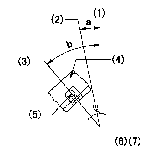
(1)Pump vertical direction
(2)Coupling's key groove position at No 1 cylinder's beginning of injection
(3)At the No 1 cylinder's beginning of injection position, stamp an aligning mark on the damper to align with the pointer's groove.
(4)Damper
(5)Pointer
(6)B.T.D.C.: aa
(7)Pre-stroke: bb
----------
aa=3deg bb=8.5+-0.03mm
----------
a=(1deg) b=(44deg)
----------
aa=3deg bb=8.5+-0.03mm
----------
a=(1deg) b=(44deg)
0000001501

A:Sealing position
B:Pre-stroke actuator
1. When installing the pre-stroke actuator on the pump, first tighten the installation bolts loosely, then move the actuator fully counterclockwise (viewed from the drive side).
Temporary tightening torque: 1 - 1.5 N.m (0.1 - 0.15 kgf.m)
2. Move the actuator in the clockwise direction when viewed from the drive side, and adjust so that it becomes the adjustment point of the adjustment value. Then tighten it.
Tightening torque: 7^9 N.m (0.7^0.9 kgf.m)
3. After prestroke actuator installation adjustment, simultaneously stamp both the actuator side and housing side.
----------
----------
----------
----------
0000001701

(Rs) rack sensor specifications
(C/U) control unit part number
(V) Rack sensor output voltage
(R) Rack position (mm)
1. Confirming governor output characteristics (rack 19 mm, span 6 mm)
(1)When the output voltages of the rack sensor are V1 and V2, check that the rack positions R1 and R2 in the table above are satisfied.
----------
----------
----------
----------
0000001901 RACK SENSOR

(VR) measurement voltage
(I) Part number of the control unit
(G) Apply red paint.
(H): End surface of the pump
1. Rack sensor adjustment (154610-0620)
(1)At governor side rack sensor output voltage V1, adjust the bobbin (A) so that the drive side rack sensor output voltage is VR+-0.01.
(2)Apply G at two places.
Connecting part between the joint (B) and the nut (F)
Connecting part between the joint (B) and the end surface of the pump (H)
----------
V1=1.6V
----------
----------
V1=1.6V
----------
Information:
In this service manual, the Mitsubishi Diesel Engine (standard model for land use) specifications, maintenance standards and adjustment procedure as well as service procedures such as disassembly, inspection, repair and reassembly are arranged in groups for quick reference. There are separate manuals for the fuel injection pump, governor and turbocharger.A short summary of each group is given in the General Contents, and there is also a table of contents at the beginning of each group.Regarding engine operation and periodical maintenance, refer to the Operation & Maintenance Manual. For component parts and ordering of service parts, refer to the Parts Catalog. Structure and function of the engine are described in various training manuals.Methods of Indication
(1) Parts shown in illustrations and described in text are numbered to correspond with the sequence of disassembly.(2) Inspections to be conducted during disassembly are indicated in a box
in disassembled views.(3) Maintenance standards for inspection and repair are described in text where they are relevant, are also listed in Group 1 in the General Contents.(4) The sequence in which parts are to be assembled is summarized below each assembled view. Such as:
(5) The following marks are used in this manual to emphasize important safety cautions.
Indicates a highly hazardous situation which, if not avoided, can result in death or serious injury.
Indicates a potentially hazardous situation which, if not avoided, can result in death or serious injury.
Indicates a potentially hazardous situation which, if not avoided, can result in minor or moderate injury.
Indicates a potentially hazardous situation which, if not avoided, can result in property damage. Note: Indicates important information or information which is useful for engine operation or maintenance.(6) Tightening torque under wet conditions is indicated as, "[Wet]". When so indicated, apply engine oil to the threaded portion of the fastener. Unless indicated as such, the tightening torque is to be assumed in the dry condition.Terms Used in This Manual
Nominal value - Indicates the standard dimension of a part to be measured.Standard - Indicates the dimension of a part, the clearance between parts, or the standard performance. Since the value is indicated in a range needed for inspection, it is different from the design value.Limit - A part must be repaired or replaced with a new part when it reaches the limit value.Abbreviations, Standard, Etc.
* BTDC = Before Top Dead Center* ATDC = After Top Dead Center* BBDC = Before Bottom Dead Center* ABDC = After Bottom Dead Center* TIR = Total Indicated Reading* API = American Petroleum Institute* ASTM = American Society for Testing and Materials* JIS = Japanese Industrial Standards* LLC = Long Life Coolant* MIL = Military Specifications and Standards (U.S.)* MSDS = Material Safety Data Sheet* SAE = Society of Automotive Engineers (U.S.)Units of Measurement
Measurements are based on the International System of Units (SI), and their converted metric values are indicated in parentheses ( ). For metric conversion, the following rates are used.* Pressure: 1 MPa = 10.197 kgf/cm2* Torque: 1 N m = 0.10197 kgf m* Force: 1 N
Have questions with 108622-2402?
Group cross 108622-2402 ZEXEL
Mitsubishi
Mitsubishi
108622-2402
F 01G 09U 1C5
ME355478
INJECTION-PUMP ASSEMBLY
6D24T2
6D24T2