Information injection-pump assembly
BOSCH
9 400 612 863
9400612863
ZEXEL
108622-2070
1086222070
Rating:
Service parts 108622-2070 INJECTION-PUMP ASSEMBLY:
1.
_
5.
AUTOM. ADVANCE MECHANIS
6.
COUPLING PLATE
7.
COUPLING PLATE
11.
Nozzle and Holder
ME151252
12.
Open Pre:MPa(Kqf/cm2)
17.7{180}/24.5{250}
14.
NOZZLE
Include in #1:
108622-2070
as INJECTION-PUMP ASSEMBLY
Cross reference number
BOSCH
9 400 612 863
9400612863
ZEXEL
108622-2070
1086222070
Zexel num
Bosch num
Firm num
Name
Calibration Data:
Adjustment conditions
Test oil
1404 Test oil ISO4113 or {SAEJ967d}
1404 Test oil ISO4113 or {SAEJ967d}
Test oil temperature
degC
40
40
45
Nozzle and nozzle holder
105780-8250
Bosch type code
1 688 901 101
Nozzle
105780-0120
Bosch type code
1 688 901 990
Nozzle holder
105780-2190
Opening pressure
MPa
20.7
Opening pressure
kgf/cm2
211
Injection pipe
Outer diameter - inner diameter - length (mm) mm 8-3-600
Outer diameter - inner diameter - length (mm) mm 8-3-600
Overflow valve
131425-0220
Overflow valve opening pressure
kPa
157
123
191
Overflow valve opening pressure
kgf/cm2
1.6
1.25
1.95
Tester oil delivery pressure
kPa
255
255
255
Tester oil delivery pressure
kgf/cm2
2.6
2.6
2.6
PS/ACT control unit part no.
407980-2
24*
Digi switch no.
31
Direction of rotation (viewed from drive side)
Right R
Right R
Injection timing adjustment
Direction of rotation (viewed from drive side)
Right R
Right R
Injection order
1-5-3-6-
2-4
Pre-stroke
mm
8.5
8.47
8.53
Beginning of injection position
Governor side NO.1
Governor side NO.1
Difference between angles 1
Cal 1-5 deg. 60 59.75 60.25
Cal 1-5 deg. 60 59.75 60.25
Difference between angles 2
Cal 1-3 deg. 120 119.75 120.25
Cal 1-3 deg. 120 119.75 120.25
Difference between angles 3
Cal 1-6 deg. 180 179.75 180.25
Cal 1-6 deg. 180 179.75 180.25
Difference between angles 4
Cyl.1-2 deg. 240 239.75 240.25
Cyl.1-2 deg. 240 239.75 240.25
Difference between angles 5
Cal 1-4 deg. 300 299.75 300.25
Cal 1-4 deg. 300 299.75 300.25
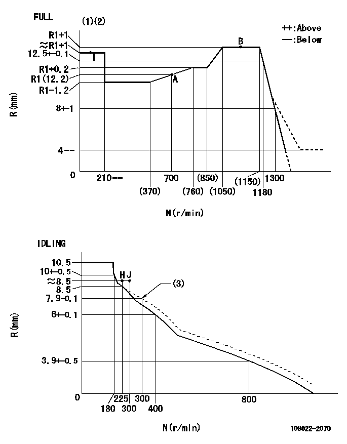
Injection quantity adjustment
Adjusting point
-
Rack position
12.2
Pump speed
r/min
700
700
700
Average injection quantity
mm3/st.
118.5
116.9
120.1
Max. variation between cylinders
%
0
-2
2
Basic
*
Fixing the rack
*
PS407980-224*
V
2.45+-0.
01
PS407980-224*
mm
6.1+-0.0
5
Standard for adjustment of the maximum variation between cylinders
*
Injection quantity adjustment_02
Adjusting point
Z
Rack position
8.5+-0.5
Pump speed
r/min
325
325
325
Average injection quantity
mm3/st.
20
18
22
Max. variation between cylinders
%
0
-15
15
Fixing the rack
*
PS407980-224*
V
V1+0.05+
-0.01
PS407980-224*
mm
8.4+-0.0
3
Standard for adjustment of the maximum variation between cylinders
*
Remarks
Refer to items regarding the pre-stroke actuator
Refer to items regarding the pre-stroke actuator
Injection quantity adjustment_03
Adjusting point
A
Rack position
R1(12.2)
Pump speed
r/min
700
700
700
Average injection quantity
mm3/st.
118.5
117.5
119.5
Basic
*
Fixing the lever
*
PS407980-224*
V
2.45+-0.
01
PS407980-224*
mm
6.1+-0.0
5
Injection quantity adjustment_04
Adjusting point
B
Rack position
R1+1
Pump speed
r/min
1100
1100
1100
Average injection quantity
mm3/st.
113
109
117
Fixing the lever
*
PS407980-224*
V
2.45+-0.
01
PS407980-224*
mm
6.1+-0.0
5
0000001601
Pre-stroke
mm
8.5
8.47
8.53
Remarks
When the timing sleeve is pushed up
When the timing sleeve is pushed up
_02
Connector angle
deg.
8.5
8
9
Remarks
When the eccentric pin is tightened
When the eccentric pin is tightened
_03
Supply voltage
V
24
23.5
24.5
Ambient temperature
degC
23
18
28
Pre-stroke
mm
6.1
6.05
6.15
Output voltage
V
2.45
2.44
2.46
Adjustment
*
_04
Supply voltage
V
24
23.5
24.5
Ambient temperature
degC
23
18
28
Pre-stroke
mm
8.5
8.47
8.53
Output voltage
V
1.2
1
1.4
Confirmation
*
Remarks
Output voltage V1
Output voltage V1
_05
Supply voltage
V
24
23.5
24.5
Ambient temperature
degC
23
18
28
Pre-stroke
mm
5.5
Output voltage
V
3
2.98
3
Confirmation
*
_06
Supply voltage
V
24
23.5
24.5
Ambient temperature
degC
23
18
28
Output voltage
V
3.05
3.05
Confirmation of operating range
*
Test data Ex:
Governor adjustment
N:Pump speed
R:Rack position (mm)
(1)Torque cam stamping: T1
(2)Tolerance for racks not indicated: +-0.05mm.
(3)Damper spring setting
----------
T1=AC06
----------
----------
T1=AC06
----------
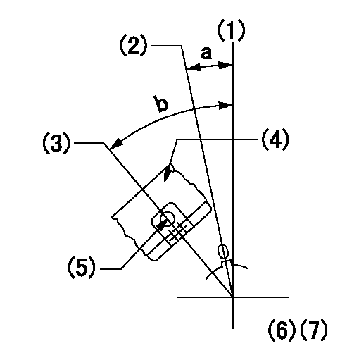
Speed control lever angle
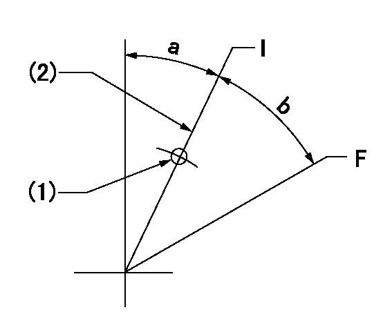
F:Full speed
I:Idle
(1)Use the hole at R = aa
(2)Stopper bolt setting
----------
aa=45mm
----------
a=30deg+-5deg b=28deg+-3deg
----------
aa=45mm
----------
a=30deg+-5deg b=28deg+-3deg
Stop lever angle
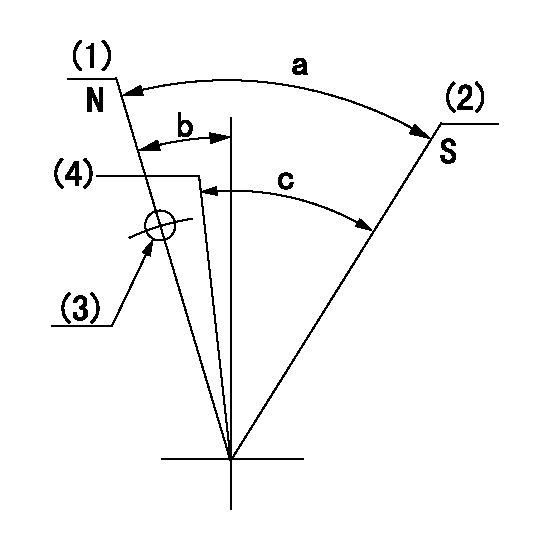
N:Pump normal
S:Stop the pump.
(1)-
(2)Set the stopper bolt at speed = aa and rack position = bb and confirm non-injection.
(3)Use the hole above R = cc
(4)Normal engine position (equivalent to R = dd).
----------
aa=1100r/min bb=3.5+-0.3mm cc=33.5mm dd=18mm
----------
a=41deg+-5deg b=25.5deg+-5deg c=(31deg)+-5deg
----------
aa=1100r/min bb=3.5+-0.3mm cc=33.5mm dd=18mm
----------
a=41deg+-5deg b=25.5deg+-5deg c=(31deg)+-5deg
0000001301
(1)Pump vertical direction
(2)Coupling's key groove position at No 1 cylinder's beginning of injection
(3)At the No 1 cylinder's beginning of injection position, stamp an aligning mark on the damper to align with the pointer's groove.
(4)Damper
(5)Pointer
(6)B.T.D.C.: aa
(7)Pre-stroke: bb
----------
aa=4deg bb=8.5+-0.03mm
----------
a=(0deg) b=(44deg)
----------
aa=4deg bb=8.5+-0.03mm
----------
a=(0deg) b=(44deg)
0000001901

A:Sealing position
B:Pre-stroke actuator
1. When installing the pre-stroke actuator on the pump, first tighten the installation bolts loosely, then move the actuator fully counterclockwise (viewed from the drive side).
Temporary tightening torque: 1 - 1.5 N.m (0.1 - 0.15 kgf.m)
2. Move the actuator in the clockwise direction when viewed from the drive side, and adjust so that it becomes the adjustment point of the adjustment value. Then tighten it.
Tightening torque: 7^9 N.m (0.7^0.9 kgf.m)
3. After prestroke actuator installation adjustment, simultaneously stamp both the actuator side and housing side.
----------
----------
----------
----------
0000002201 RACK SENSOR

(VR) measurement voltage
(I) Part number of the control unit
(G) Apply red paint.
(H): End surface of the pump
1. Rack sensor adjustment (-0620)
(1)Fix the speed control lever at the full position
(2)Set the speed to N1 r/min.
(If the boost compensator is provided, apply boost pressure.)
(3)Adjust the bobbin (A) so that the rack sensor's output voltage is VR+-0.01.
(4)At that time, rack position must be Ra.
(5)Apply G at two places.
Connecting part between the joint (B) and the nut (F)
Connecting part between the joint (B) and the end surface of the pump (H)
----------
N1=1100r/min Ra=R1(12.2)+1mm
----------
----------
N1=1100r/min Ra=R1(12.2)+1mm
----------
0000002301 MICRO SWITCH
Adjustment of the micro-switch
Adjust the bolt to obtain the following lever position when the micro-switch is ON.
(1)Speed N1
(2)Rack position Ra
----------
N1=325r/min Ra=8+-0.1mm
----------
----------
N1=325r/min Ra=8+-0.1mm
----------
Information:
AUGUST 2011
INFORMATION RELEASE MEMO
Reman
PELJ1306 ?2011 Caterpillar REMAN DIESEL PARTICULATE FILTERS FOR MACHINE APPLICATIONS
To provide our customers with cost effective service options to support their Tier 4 emissions engines, Cat Reman has released a Reman version of the diesel particulate filters (DPF) used on many Tier 4 Cat? machines. The DPF traps both soot and ash. Soot is removed through a regeneration process outlined in the machines operation and maintenance manual. Ash that accumulates from engine oil is removed through a cleaning procedure that requires removal of the DPF from the machine. The cleaning procedure requires the DPF to be removed from the machine. Special Instruction REHS5045 outlines the three approved processes for performing the required Diesel Particulate Filter (DPF) maintenance on Tier 4 products equipped with a DPF.
Replacement of the existing DPF with a new Cat DPF
Replacement of the existing DPF with a remanufactured Cat DPF
Removal of the existing DPF and having the DPF cleaned by a Cat approved cleaning device.
The Reman DPFs listed below are available to support these maintenance requirements:
Core Acceptance
After gaining some experience with the previously released DPFs used for on-highway engines and to support the launch of these additional machine DPFs, we have changed some of the inspection criteria and issued a revision to SELD0292. SELD0292-02 Caterpillar Diesel Particulate Filter (DPF) is the current Core Acceptance Criteria (CAC). It is critical to avoid non-operational damage that can decrease the value of the cores. Encourage service technicians to handle and package the cores with care so they will be more likely to be eligible for the full core refunds. Please always refer to the most current version at catreman.cat.com/core to view the latest requirements. The acceptability inspection for these is a simple visual inspection based on the following guidelines:
Warranty
All Reman products carry the same warranty as new parts. Please consult the appropriate warranty statement for your area.
Core Management
Please refer to the Cat Core Management Information System (CMIS 2) related to the parts information application that describes all Reman part/Core Acceptability Family (CAF) and other related information. Also refer to other CMIS 2 inquiry applications such as: Dealer Customer Profile, Inspection Reason Codes, Inspection Line Inquiry, Dealer Add Charges, Dealer Entitlement Activity, Dealer CCR Inquiry, Dealer CCR Entry, Dealer Shipment Processing, Dealer Process Packaging Grief and Reporting. This information is available to all dealers worldwide that have been converted to CMIS 2.
Please go to the Reman web site https://catreman.cat.com for the latest policy and procedural updates that are available to all dealers worldwide explaining policy and procedural information such as Policy and Core Management SELD0122 -10, "Core Management Systems and Operations Procedures SELD0040-14, "Reman Core Return Packaging Instructions And Guidelines SELD0300-00 and "Shipping Instructions" SELD0039-14.
If you have any questions regarding Reman Core Management or Core Management Systems (CMIS2),