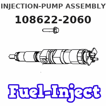
Information injection-pump assembly
BOSCH
9 400 612 861
9400612861
ZEXEL
108622-2060
1086222060
Rating:
Service parts 108622-2060 INJECTION-PUMP ASSEMBLY:
1.
_
5.
AUTOM. ADVANCE MECHANIS
6.
COUPLING PLATE
7.
COUPLING PLATE
11.
Nozzle and Holder
ME151252
12.
Open Pre:MPa(Kqf/cm2)
17.7{180}/24.5{250}
14.
NOZZLE
Include in #1:
108622-2060
as INJECTION-PUMP ASSEMBLY
Cross reference number
BOSCH
9 400 612 861
9400612861
ZEXEL
108622-2060
1086222060
Zexel num
Bosch num
Firm num
Name
Calibration Data:
Adjustment conditions
Test oil
1404 Test oil ISO4113 or {SAEJ967d}
1404 Test oil ISO4113 or {SAEJ967d}
Test oil temperature
degC
40
40
45
Nozzle and nozzle holder
105780-8250
Bosch type code
1 688 901 101
Nozzle
105780-0120
Bosch type code
1 688 901 990
Nozzle holder
105780-2190
Opening pressure
MPa
20.7
Opening pressure
kgf/cm2
211
Injection pipe
Outer diameter - inner diameter - length (mm) mm 8-3-600
Outer diameter - inner diameter - length (mm) mm 8-3-600
Overflow valve
131425-0220
Overflow valve opening pressure
kPa
157
123
191
Overflow valve opening pressure
kgf/cm2
1.6
1.25
1.95
Tester oil delivery pressure
kPa
255
255
255
Tester oil delivery pressure
kgf/cm2
2.6
2.6
2.6
RED3 control unit part number
407910-2
470
RED3 rack sensor specifications
mm
15
PS/ACT control unit part no.
407980-2
24*
Digi switch no.
31
Direction of rotation (viewed from drive side)
Right R
Right R
Injection timing adjustment
Direction of rotation (viewed from drive side)
Right R
Right R
Injection order
1-5-3-6-
2-4
Pre-stroke
mm
8.5
8.47
8.53
Beginning of injection position
Governor side NO.1
Governor side NO.1
Difference between angles 1
Cal 1-5 deg. 60 59.75 60.25
Cal 1-5 deg. 60 59.75 60.25
Difference between angles 2
Cal 1-3 deg. 120 119.75 120.25
Cal 1-3 deg. 120 119.75 120.25
Difference between angles 3
Cal 1-6 deg. 180 179.75 180.25
Cal 1-6 deg. 180 179.75 180.25
Difference between angles 4
Cyl.1-2 deg. 240 239.75 240.25
Cyl.1-2 deg. 240 239.75 240.25
Difference between angles 5
Cal 1-4 deg. 300 299.75 300.25
Cal 1-4 deg. 300 299.75 300.25
Injection quantity adjustment
Rack position
(11.2)
Vist
V
1.76
1.76
1.76
Pump speed
r/min
700
700
700
Average injection quantity
mm3/st.
127.5
126.5
128.5
Max. variation between cylinders
%
0
-2
2
Basic
*
PS407980-224*
V
2.45+-0.
01
PS407980-224*
mm
6.1+-0.0
5
Injection quantity adjustment_02
Rack position
(7)
Vist
V
2.6
2.5
2.7
Pump speed
r/min
325
325
325
Average injection quantity
mm3/st.
20
18
22
Max. variation between cylinders
%
0
-15
15
PS407980-224*
V
V1+0.05+
-0.01
PS407980-224*
mm
8.4+-0.0
3
Remarks
Refer to items regarding the pre-stroke actuator
Refer to items regarding the pre-stroke actuator
0000001201
Pre-stroke
mm
8.5
8.47
8.53
Remarks
When the timing sleeve is pushed up
When the timing sleeve is pushed up
_02
Connector angle
deg.
8.5
8
9
Remarks
When the eccentric pin is tightened
When the eccentric pin is tightened
_03
Supply voltage
V
24
23.5
24.5
Ambient temperature
degC
23
18
28
Pre-stroke
mm
6.1
6.05
6.15
Output voltage
V
2.45
2.44
2.46
Adjustment
*
_04
Supply voltage
V
24
23.5
24.5
Ambient temperature
degC
23
18
28
Pre-stroke
mm
8.5
8.47
8.53
Output voltage
V
1.2
1
1.4
Confirmation
*
Remarks
Output voltage V1
Output voltage V1
_05
Supply voltage
V
24
23.5
24.5
Ambient temperature
degC
23
18
28
Pre-stroke
mm
5.5
Output voltage
V
3
2.98
3
Confirmation
*
_06
Supply voltage
V
24
23.5
24.5
Ambient temperature
degC
23
18
28
Output voltage
V
3.05
3.05
Confirmation of operating range
*
Test data Ex:
Speed control lever angle
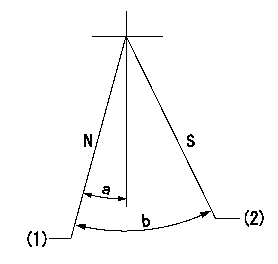
N:Pump normal
S:Stop the pump.
(1)Rack position = aa
(2)Rack position bb
----------
aa=16mm bb=1mm
----------
a=3deg+-5deg b=29deg+-5deg
----------
aa=16mm bb=1mm
----------
a=3deg+-5deg b=29deg+-5deg
0000000901
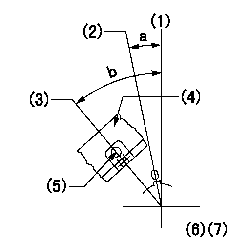
(1)Pump vertical direction
(2)Coupling's key groove position at No 1 cylinder's beginning of injection
(3)At the No 1 cylinder's beginning of injection position, stamp an aligning mark on the damper to align with the pointer's groove.
(4)Damper
(5)Pointer
(6)B.T.D.C.: aa
(7)Pre-stroke: bb
----------
aa=4deg bb=8.5+-0.03mm
----------
a=(0deg) b=(44deg)
----------
aa=4deg bb=8.5+-0.03mm
----------
a=(0deg) b=(44deg)
0000001501

A:Sealing position
B:Pre-stroke actuator
1. When installing the pre-stroke actuator on the pump, first tighten the installation bolts loosely, then move the actuator fully counterclockwise (viewed from the drive side).
Temporary tightening torque: 1 - 1.5 N.m (0.1 - 0.15 kgf.m)
2. Move the actuator in the clockwise direction when viewed from the drive side, and adjust so that it becomes the adjustment point of the adjustment value. Then tighten it.
Tightening torque: 7^9 N.m (0.7^0.9 kgf.m)
3. After prestroke actuator installation adjustment, simultaneously stamp both the actuator side and housing side.
----------
----------
----------
----------
0000001701

(Rs) rack sensor specifications
(C/U) control unit part number
(V) Rack sensor output voltage
(R) Rack position (mm)
1. Confirming governor output characteristics (rack 15 mm, span 6 mm)
(1)When the output voltages of the rack sensor are V1 and V2, check that the rack positions R1 and R2 in the table above are satisfied.
----------
----------
----------
----------
0000001901 RACK SENSOR

(VR) measurement voltage
(I) Part number of the control unit
(G) Apply red paint.
(H): End surface of the pump
1. Rack sensor adjustment (154610-0620)
(1)At governor side rack sensor output voltage V1, adjust the bobbin (A) so that the drive side rack sensor output voltage is VR+-0.01.
(2)Apply G at two places.
Connecting part between the joint (B) and the nut (F)
Connecting part between the joint (B) and the end surface of the pump (H)
----------
V1=1V
----------
----------
V1=1V
----------
Information:
SEPTEMBER 2009
INFORMATION RELEASE MEMO
Reman
PELJ1080 ?2009 Caterpillar
CAT REMAN ANNOUNCES THE INTRODUCTION OF AN UPGRADE TO NEW INJECTOR KIT FOR CERTAIN HIGH DISPLACEMENT 3500 ENGINES IN MINING APPLICATIONS
Announcement
Some mining customers have expressed a preference to use new fuel injectors during an engine rebuild as part of a bill of materials designed to produce a "zero" hour rebuilt engine standard. To provide an economical option to those customers, Cat Reman announces the introduction of an Upgrade to New (UTN) fuel injector kit option for certain 3500 engines in mining applications. This option will meet the customer need while enabling Cat Reman to capture the cores of those customers using new injectors.
These fuel injector kits will provide dealers and customers with an additional fuel injector replacement and repair option and come complete with four new fuel injectors and corresponding hold down bolts. Refer to the following table for part number details.
甀
Availability and Ordering
To support availability of these UTN kits for planned rebuilds, we ask dealers to place Future Dated Orders (FDOs) whenever possible.
Core Acceptance
Core Acceptance Criteria for CatP?PFuel Injectors is simple, visual, and requires no special tools. Consult the Unit Injectors ? Electronic Core Acceptance Criteria SELD0226 for complete details. The purchase of an UTN Kit establishes core entitlements at the consist part level quantity. For example, purchase of a kit of four UTN Injectors establishes four individual core injector entitlements.
Warranty
Please consult the appropriate CatP Pparts warranty statement for your area.
Core Management
Please refer to the Caterpillar Core Management Information System (CMIS 2) related to the parts information application that describes all Reman part/Core Acceptability Family (CAF) and other related information. Also refer to other CMIS 2 inquiry applications such as: Dealer Customer Profile, Inspection Reason Codes, Inspection Line Inquiry, Dealer Add Charges, Dealer Entitlement Activity, Dealer CCR Inquiry, Dealer CCR Entry, Dealer Shipment Processing, Dealer Process Packaging Grief and Reporting. This information is available to all dealers worldwide that have been converted to CMIS 2.
Please go to the Reman web site https://catreman.cat.com for your assigned Core Help Line Contact Information; the latest policy and procedural updates that are available to all dealers worldwide explaining policy and procedural information such as Policy and Core Management SELD0122 -10, "Core Management Systems and Operations Procedures SELD0040-14, "Reman Core Return Packaging Instructions And Guidelines SELD0300-00 and "Shipping Instructions" SELD0039-14.
If you have any questions regarding Reman Core Management or Core Management Information Systems (CMIS2), feel free to call your Corinth Dealer Service Representative toll free at (800) 537-2928. Outside the US please refer to the Core section of the Reman website for appropriate contact information for your region.
For assistance with technical questions, call the Peoria Reman Technical Help Line toll free at (888) 88-REMAN (outside the US call non-toll free +1-309-494-4342), or use our E-mail address--Reman_Help.