Information injection-pump assembly
BOSCH
9 400 619 128
9400619128
ZEXEL
108622-2013
1086222013
MITSUBISHI
ME150698
me150698

Rating:
Cross reference number
BOSCH
9 400 619 128
9400619128
ZEXEL
108622-2013
1086222013
MITSUBISHI
ME150698
me150698
Zexel num
Bosch num
Firm num
Name
108622-2013
9 400 619 128
ME150698 MITSUBISHI
INJECTION-PUMP ASSEMBLY
E81X K
E81X K
Calibration Data:
Adjustment conditions
Test oil
1404 Test oil ISO4113 or {SAEJ967d}
1404 Test oil ISO4113 or {SAEJ967d}
Test oil temperature
degC
40
40
45
Nozzle and nozzle holder
105780-8250
Bosch type code
1 688 901 101
Nozzle
105780-0120
Bosch type code
1 688 901 990
Nozzle holder
105780-2190
Opening pressure
MPa
20.7
Opening pressure
kgf/cm2
211
Injection pipe
Outer diameter - inner diameter - length (mm) mm 8-3-600
Outer diameter - inner diameter - length (mm) mm 8-3-600
Overflow valve
131425-0220
Overflow valve opening pressure
kPa
157
123
191
Overflow valve opening pressure
kgf/cm2
1.6
1.25
1.95
Tester oil delivery pressure
kPa
255
255
255
Tester oil delivery pressure
kgf/cm2
2.6
2.6
2.6
PS/ACT control unit part no.
407980-2
24*
Digi switch no.
31
Direction of rotation (viewed from drive side)
Right R
Right R
Injection timing adjustment
Direction of rotation (viewed from drive side)
Right R
Right R
Injection order
1-5-3-6-
2-4
Pre-stroke
mm
8.5
8.47
8.53
Beginning of injection position
Governor side NO.1
Governor side NO.1
Difference between angles 1
Cal 1-5 deg. 60 59.75 60.25
Cal 1-5 deg. 60 59.75 60.25
Difference between angles 2
Cal 1-3 deg. 120 119.75 120.25
Cal 1-3 deg. 120 119.75 120.25
Difference between angles 3
Cal 1-6 deg. 180 179.75 180.25
Cal 1-6 deg. 180 179.75 180.25
Difference between angles 4
Cyl.1-2 deg. 240 239.75 240.25
Cyl.1-2 deg. 240 239.75 240.25
Difference between angles 5
Cal 1-4 deg. 300 299.75 300.25
Cal 1-4 deg. 300 299.75 300.25
Injection quantity adjustment
Adjusting point
-
Rack position
13.5
Pump speed
r/min
700
700
700
Average injection quantity
mm3/st.
128.5
126.9
130.1
Max. variation between cylinders
%
0
-2
2
Basic
*
Fixing the rack
*
PS407980-224*
V
2.45+-0.
01
PS407980-224*
mm
6.1+-0.0
5
Standard for adjustment of the maximum variation between cylinders
*
Injection quantity adjustment_02
Adjusting point
Z
Rack position
8.5+-0.5
Pump speed
r/min
320
320
320
Average injection quantity
mm3/st.
20
18
22
Max. variation between cylinders
%
0
-15
15
Fixing the rack
*
PS407980-224*
V
V1+0.05+
-0.01
PS407980-224*
mm
8.4+-0.0
3
Standard for adjustment of the maximum variation between cylinders
*
Remarks
Refer to items regarding the pre-stroke actuator
Refer to items regarding the pre-stroke actuator
Injection quantity adjustment_03
Adjusting point
A
Rack position
R1(13.5)
Pump speed
r/min
700
700
700
Average injection quantity
mm3/st.
128.5
127.5
129.5
Basic
*
Fixing the lever
*
PS407980-224*
V
2.45+-0.
01
PS407980-224*
mm
6.1+-0.0
5
Injection quantity adjustment_04
Adjusting point
B
Rack position
R1+1.3
Pump speed
r/min
1100
1100
1100
Average injection quantity
mm3/st.
126.5
122.5
130.5
Fixing the lever
*
PS407980-224*
V
2.45+-0.
01
PS407980-224*
mm
6.1+-0.0
5
0000001601
Pre-stroke
mm
8.5
8.47
8.53
Remarks
When the timing sleeve is pushed up
When the timing sleeve is pushed up
_02
Connector angle
deg.
8.5
8
9
Remarks
When the eccentric pin is tightened
When the eccentric pin is tightened
_03
Supply voltage
V
24
23.5
24.5
Ambient temperature
degC
23
18
28
Pre-stroke
mm
6.1
6.05
6.15
Output voltage
V
2.45
2.44
2.46
Adjustment
*
_04
Supply voltage
V
24
23.5
24.5
Ambient temperature
degC
23
18
28
Pre-stroke
mm
8.5
8.47
8.53
Output voltage
V
1.2
1
1.4
Confirmation
*
Remarks
Output voltage V1
Output voltage V1
_05
Supply voltage
V
24
23.5
24.5
Ambient temperature
degC
23
18
28
Pre-stroke
mm
5.5
Output voltage
V
3
2.98
3
Confirmation
*
_06
Supply voltage
V
24
23.5
24.5
Ambient temperature
degC
23
18
28
Output voltage
V
3.05
3.05
Confirmation of operating range
*
Test data Ex:
Governor adjustment
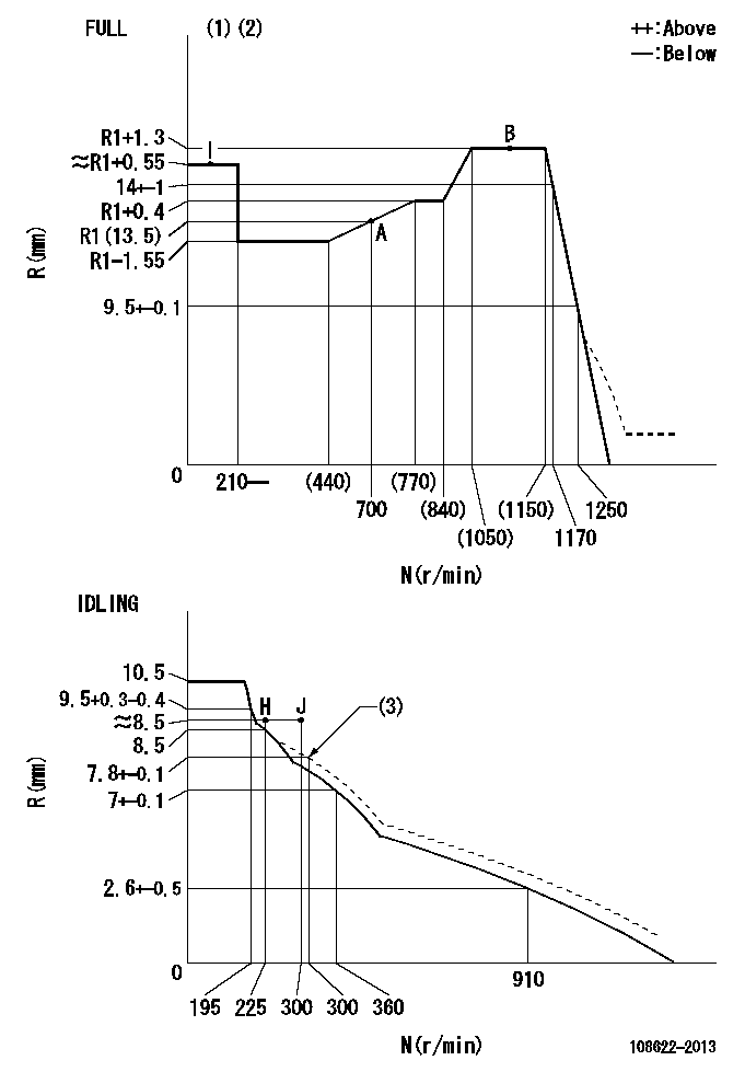
N:Pump speed
R:Rack position (mm)
(1)Torque cam stamping: T1
(2)Tolerance for racks not indicated: +-0.05mm.
(3)Damper spring setting
----------
T1=AB32
----------
----------
T1=AB32
----------
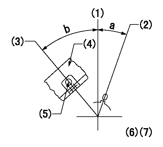
Speed control lever angle

F:Full speed
I:Idle
(1)Use the hole at R = aa
(2)Stopper bolt set position 'H'
(3)Viewed from feed pump side.
----------
aa=34.5mm
----------
a=25deg+-5deg b=38deg+-3deg
----------
aa=34.5mm
----------
a=25deg+-5deg b=38deg+-3deg
Stop lever angle

N:Pump normal
S:Stop the pump.
(1)At pump speed aa and rack position bb, set the stopper bolt. (Confirm non-injection.)
(2)Normal engine position (Rack position corresponding to cc)
(3)Use the hole above R = dd
----------
aa=1100r/min bb=3.5+-0.3mm cc=18mm dd=33.5mm
----------
a=41deg+-5deg b=25.5deg+-5deg c=(31deg)+-5deg
----------
aa=1100r/min bb=3.5+-0.3mm cc=18mm dd=33.5mm
----------
a=41deg+-5deg b=25.5deg+-5deg c=(31deg)+-5deg
0000001301
(1)Pump vertical direction
(2)Coupling's key groove position at No 1 cylinder's beginning of injection
(3)At the No 1 cylinder's beginning of injection position, stamp an aligning mark on the damper to align with the pointer's groove.
(4)Damper
(5)Pointer
(6)B.T.D.C.: aa
(7)Pre-stroke: bb
----------
aa=4deg bb=8.5+-0.03mm
----------
a=(0deg) b=(44deg)
----------
aa=4deg bb=8.5+-0.03mm
----------
a=(0deg) b=(44deg)
0000001901

A:Sealing position
B:Pre-stroke actuator
1. When installing the pre-stroke actuator on the pump, first tighten the installation bolts loosely, then move the actuator fully counterclockwise (viewed from the drive side).
Temporary tightening torque: 1 - 1.5 N.m (0.1 - 0.15 kgf.m)
2. Move the actuator in the clockwise direction when viewed from the drive side, and adjust so that it becomes the adjustment point of the adjustment value. Then tighten it.
Tightening torque: 7^9 N.m (0.7^0.9 kgf.m)
3. After prestroke actuator installation adjustment, simultaneously stamp both the actuator side and housing side.
----------
----------
----------
----------
0000002201 MICRO SWITCH
Adjustment of the micro-switch
Adjust the bolt to obtain the following lever position when the micro-switch is ON.
(1)Speed N1
(2)Rack position Ra
----------
N1=330r/min Ra=8+-0.1mm
----------
----------
N1=330r/min Ra=8+-0.1mm
----------
0000002301 RACK SENSOR

(VR) measurement voltage
(I) Part number of the control unit
(G) Apply red paint.
(H): End surface of the pump
1. Rack sensor adjustment (-0620)
(1)Fix the speed control lever at the full position
(2)Set the speed to N1 r/min.
(If the boost compensator is provided, apply boost pressure.)
(3)Adjust the bobbin (A) so that the rack sensor's output voltage is VR+-0.01.
(4)At that time, rack position must be Ra.
(5)Apply G at two places.
Connecting part between the joint (B) and the nut (F)
Connecting part between the joint (B) and the end surface of the pump (H)
----------
N1=1100r/min Ra=R1(13.5)+1.3mm
----------
----------
N1=1100r/min Ra=R1(13.5)+1.3mm
----------
Information:
REM06-41
Reman
November 2006 REMAN FUEL INJECTORS FOR VARIOUS MACHINE, INDUSTRIAL AND ON-HIGHWAY TRUCK APPLICATIONS AnnouncementThe Remanufacturing Division announces the addition of the following Remanufactured Fuel Injectors to complement the existing product offerings for various machine, industrial and on-highway truck applications. CoverageThe addition of these Reman Fuel Injectors provides dealers with a lower cost repair option. The table below lists coverage by part number.
Reman Part Number New Part Number Engine Model Part Name
10R3071 2490697 C13 Injector Gp- Fuel
10R3147 2490712 C11 Injector Gp- Fuel
10R3262 2490713 C11 Injector Gp- Fuel
10R3263 2530614 C15 Injector Gp- Fuel
10R3264 2530615 C15 Injector Gp- Fuel
10R3266 2530617 C27 Injector Gp- Fuel Features and BenefitsCat? Remanufactured fuel injectors offer excellent value to customers. Customers who want fast repair turn-around, superior quality and reliability, and lower repair costs will benefit from the use of these Remanufactured fuel injectors. Cat Remanufactured fuel injectors provide immediate, off-the-shelf availability at a fraction of the new price.
Features Benefits
All critical engineering changes and updates included
Improved reliability and performance
Worldwide availability through Caterpillar parts distribution system
Customer access regardless of location
Off-the-shelf availability
Downtime reduced through exchange product
Same-as-new Caterpillar warranty
Consistent support
Core AcceptanceCore Acceptance Criteria for Caterpillar? Remanufactured fuel injectors is a simple, visual inspection, and requires no special tools. Consult our Core Acceptance Guide online for complete details.WarrantyPlease consult the appropriate warranty statement for your area.Core ManagementPlease refer to the Caterpillar? Core Management Information System (CMIS 2) Parts Information application describing all reman part/CAF and related information. Also refer to other CMIS 2 inquiry applications such as Customer Profiles, Inspection Reason Codes, Inspection Line Inquiry, Add Charge Information, Entitlement Activity, Entitlement Inquiry, CCR Inquiry, CCR Entry, Shipment Processing; Process Packaging Grief; and Reporting to properly manage core returns and monitor inspection performance. This information will be available to all dealers worldwide after your CMIS 2 conversion date.For the latest updates of Reman Policies and Core Management (SELD0122), Core Management Systems & Operations Procedures (SELD0040), and Shipping Instructions (SELD0039), go to the Reman website at https://reman.cat and click on Procedures and Policies (listed under Reman Program Information). If you have any questions regarding core return processing, feel free to call your Corinth Dealer Service Representative toll free at (800) 537-2928 or use our e-mail address -- reman_core_operations. For assistance with technical questions, call the Peoria Reman Customer Satisfaction Hot Line also toll free at (888) 88-REMAN or use our e-mail address -- Reman_Help.
PELJ0719 CATERPILLAR? ?2006 Caterpillar
Have questions with 108622-2013?
Group cross 108622-2013 ZEXEL
Mitsubishi
Mitsubishi
108622-2013
9 400 619 128
ME150698
INJECTION-PUMP ASSEMBLY
E81X
E81X