Information injection-pump assembly
ZEXEL
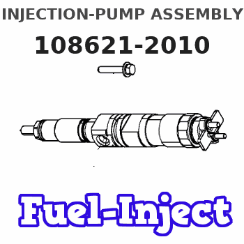
108621-2010
1086212010
Rating:
Cross reference number
ZEXEL
108621-2010
1086212010
Zexel num
Bosch num
Firm num
Name
108621-2010
INJECTION-PUMP ASSEMBLY
Calibration Data:
Adjustment conditions
Test oil
1404 Test oil ISO4113 or {SAEJ967d}
1404 Test oil ISO4113 or {SAEJ967d}
Test oil temperature
degC
40
40
45
Nozzle and nozzle holder
105780-8250
Bosch type code
1 688 901 101
Nozzle
105780-0120
Bosch type code
1 688 901 990
Nozzle holder
105780-2190
Opening pressure
MPa
20.7
Opening pressure
kgf/cm2
211
Injection pipe
Outer diameter - inner diameter - length (mm) mm 8-3-600
Outer diameter - inner diameter - length (mm) mm 8-3-600
Overflow valve
131424-7220
Overflow valve opening pressure
kPa
255
221
289
Overflow valve opening pressure
kgf/cm2
2.6
2.25
2.95
Tester oil delivery pressure
kPa
255
255
255
Tester oil delivery pressure
kgf/cm2
2.6
2.6
2.6
RED3 control unit part number
407910-2
470
RED3 rack sensor specifications
mm
15
PS/ACT control unit part no.
407980-2
24*
Digi switch no.
21
Direction of rotation (viewed from drive side)
Left L
Left L
Injection timing adjustment
Direction of rotation (viewed from drive side)
Left L
Left L
Injection order
1-5-3-6-
2-4
Pre-stroke
mm
5.6
5.57
5.63
Beginning of injection position
Governor side NO.1
Governor side NO.1
Difference between angles 1
Cal 1-5 deg. 60 59.75 60.25
Cal 1-5 deg. 60 59.75 60.25
Difference between angles 2
Cal 1-3 deg. 120 119.75 120.25
Cal 1-3 deg. 120 119.75 120.25
Difference between angles 3
Cal 1-6 deg. 180 179.75 180.25
Cal 1-6 deg. 180 179.75 180.25
Difference between angles 4
Cyl.1-2 deg. 240 239.75 240.25
Cyl.1-2 deg. 240 239.75 240.25
Difference between angles 5
Cal 1-4 deg. 300 299.75 300.25
Cal 1-4 deg. 300 299.75 300.25
Injection quantity adjustment
Rack position
(12.9)
Vist
V
1.42
1.42
1.42
Pump speed
r/min
650
650
650
Average injection quantity
mm3/st.
148.5
147.5
149.5
Max. variation between cylinders
%
0
-2
2
Basic
*
PS407980-224*
V
V1+1.44+
-0.01
PS407980-224*
mm
3.2+-0.0
5
Remarks
Refer to items regarding the pre-stroke actuator
Refer to items regarding the pre-stroke actuator
Injection quantity adjustment_02
Rack position
(6.5)
Vist
V
2.7
2.6
2.8
Pump speed
r/min
250
250
250
Average injection quantity
mm3/st.
10.5
8.5
12.5
Max. variation between cylinders
%
0
-15
15
PS407980-224*
V
V1+0.13+
-0.01
PS407980-224*
mm
5.4+-0.0
3
Governor adjustment
Pump speed
r/min
700--
Remarks
Start
Start
Governor adjustment_02
Pump speed
r/min
650
Advance angle
deg.
0.5
Governor adjustment_03
Pump speed
r/min
850
Advance angle
deg.
2
1.5
2.5
Remarks
Finish
Finish
0000001201
Pre-stroke
mm
5.6
5.57
5.63
Remarks
When the timing sleeve is pushed up
When the timing sleeve is pushed up
_02
Connector angle
deg.
5
4.5
5.5
Remarks
When the eccentric pin is tightened
When the eccentric pin is tightened
_03
Supply voltage
V
24
23.5
24.5
Ambient temperature
degC
23
18
28
Pre-stroke
mm
5.6
5.57
5.63
Output voltage
V
1
1
1.05
Adjustment
*
Remarks
Output voltage V1
Output voltage V1
_04
Supply voltage
V
24
23.5
24.5
Ambient temperature
degC
23
18
28
Pre-stroke
mm
2.6
2.32
2.88
Output voltage
V
2.8
2.78
2.87
Confirmation
*
_05
Supply voltage
V
24
23.5
24.5
Ambient temperature
degC
23
18
28
Output voltage
V
3.05
3.05
Confirmation of operating range
*
Test data Ex:
Speed control lever angle

N:Pump normal
S:Stop the pump.
(1)Rack position = aa
(2)Rack position bb
----------
aa=16mm bb=1mm
----------
a=19deg+-5deg b=29deg+-5deg
----------
aa=16mm bb=1mm
----------
a=19deg+-5deg b=29deg+-5deg
0000000901

(1)Pump vertical direction
(2)Coupling's key groove position at No 1 cylinder's beginning of injection
(3)Pre-stroke: aa
(4)-
----------
aa=5.6+-0.03mm
----------
a=(2deg)
----------
aa=5.6+-0.03mm
----------
a=(2deg)
0000001701

(Rs) rack sensor specifications
(C/U) control unit part number
(V) Rack sensor output voltage
(R) Rack position (mm)
1. Confirming governor output characteristics (rack 15 mm, span 6 mm)
(1)When the output voltages of the rack sensor are V1 and V2, check that the rack positions R1 and R2 in the table above are satisfied.
----------
----------
----------
----------
Information:
Solution
Caterpillar is aware of this problem and is recommending the following interim corrective action. Please follow the Special Instruction, M0110497, "Removal and Installation Procedure for DEF Heated Lines on Certain Machine Engines" for proper Disassembly and Assembly of the DEF heated lines to avoid failures. If a failure or DEF leak is noted even after following the special instructions, please use Service Magazine, M0103829, "Diesel Exhaust Fluid (DEF) Heated Lines May Be Damage on Certain Cat® Machines" for a temporary line repair. If additional help is needed, please go to the Parts Tech tab and enter a Product Health ticket in PSCRM.The new hose assemblies are listed in Table 1.
Table 1
Item Qty New Part Number Part Name
1 1 457-9011 Return Hose Assembly
2 1 457-9013 Return Hose Assembly
3 1 457-9026 Return Hose Assembly
4 1 457-9027 Return Hose Assembly
5 1 462-4206 Hose As
6 1 462-4210 Hose As
7 1 462-4211 Hose As
8 1 462-4219 Hose As
9 1 462-4220 Hose As
10 1 462-4221 Hose As
11 1 462-4223 Hose As
12 1 462-4224 Hose As
13 1 475-3231 Hose As
14 1 475-3232 Hose As
15 1 475-3233 Hose As
16 1 475-3234 Hose As
17 1 475-9989 Hose As
18 1 478-9071 Hose As
19 1 478-9072 Hose As
20 1 478-9074 Hose As
21 1 478-9075 Hose As
22 1 478-9077 Hose As
23 1 478-9078 Hose As
24 1 478-9079 Hose As
25 1 478-9081 Hose As
26 1 478-9082 Hose As
27 1 478-9083 Hose As
28 1 478-9085 Hose As
29 1 478-9086 Hose As
30 1 497-9305 Hose As
31 1 497-9306 Hose As
32 1 497-9307 Hose As
33 1 497-9308 Hose As
34 1 500-6215 Return Hose Assembly
35 1 500-6216 Return Hose Assembly
36 1 500-6217 Hose As
37 1 500-6218 Hose As
38 1 500-6219 Hose As
39 1 500-6220 Hose As
40 1 500-6221 Hose As
41 1 500-6222 Hose As
42 1 500-6223 Hose As
43 1 500-6224 Hose As
44 1 510-5191 Return Hose Assembly
45 1 510-5192 Hose As
46 1 510-5193 Hose As
47 1 510-5194 Hose As
48 1 552-3292 Hose As
49 1 552-3293 Hose As
50 1 552-3294 Hose As
51 1 552-3295 Hose As
52 1 579-9200 Hose As
53 1 579-9201 Hose As
54 1 579-9202 Hose As
55 1 579-9203 Hose As
Have questions with 108621-2010?
Group cross 108621-2010 ZEXEL
108621-2010
INJECTION-PUMP ASSEMBLY