Information injection-pump assembly
ZEXEL
108621-2001
1086212001

Rating:
Cross reference number
ZEXEL
108621-2001
1086212001
Zexel num
Bosch num
Firm num
Name
108621-2001
INJECTION-PUMP ASSEMBLY
Calibration Data:
Adjustment conditions
Test oil
1404 Test oil ISO4113 or {SAEJ967d}
1404 Test oil ISO4113 or {SAEJ967d}
Test oil temperature
degC
40
40
45
Nozzle and nozzle holder
105780-8140
Bosch type code
EF8511/9A
Nozzle
105780-0000
Bosch type code
DN12SD12T
Nozzle holder
105780-2080
Bosch type code
EF8511/9
Opening pressure
MPa
17.2
Opening pressure
kgf/cm2
175
Injection pipe
Outer diameter - inner diameter - length (mm) mm 8-3-600
Outer diameter - inner diameter - length (mm) mm 8-3-600
Overflow valve
131424-7220
Overflow valve opening pressure
kPa
255
221
289
Overflow valve opening pressure
kgf/cm2
2.6
2.25
2.95
Tester oil delivery pressure
kPa
157
157
157
Tester oil delivery pressure
kgf/cm2
1.6
1.6
1.6
PS/ACT control unit part no.
407980-2
24*
Digi switch no.
21
Direction of rotation (viewed from drive side)
Left L
Left L
Injection timing adjustment
Direction of rotation (viewed from drive side)
Left L
Left L
Injection order
1-5-3-6-
2-4
Pre-stroke
mm
5.6
5.57
5.63
Beginning of injection position
Governor side NO.1
Governor side NO.1
Difference between angles 1
Cal 1-5 deg. 60 59.75 60.25
Cal 1-5 deg. 60 59.75 60.25
Difference between angles 2
Cal 1-3 deg. 120 119.75 120.25
Cal 1-3 deg. 120 119.75 120.25
Difference between angles 3
Cal 1-6 deg. 180 179.75 180.25
Cal 1-6 deg. 180 179.75 180.25
Difference between angles 4
Cyl.1-2 deg. 240 239.75 240.25
Cyl.1-2 deg. 240 239.75 240.25
Difference between angles 5
Cal 1-4 deg. 300 299.75 300.25
Cal 1-4 deg. 300 299.75 300.25
Injection quantity adjustment
Adjusting point
-
Rack position
11.2
Pump speed
r/min
700
700
700
Each cylinder's injection qty
mm3/st.
176.8
172.4
181.2
Basic
*
Fixing the rack
*
PS407980-224*
V
V1+0.13+
-0.01
PS407980-224*
mm
5.4+-0.0
3
Standard for adjustment of the maximum variation between cylinders
*
Remarks
Refer to items regarding the pre-stroke actuator
Refer to items regarding the pre-stroke actuator
Injection quantity adjustment_02
Adjusting point
C
Rack position
5.3+-0.5
Pump speed
r/min
250
250
250
Each cylinder's injection qty
mm3/st.
11.6
9.9
13.3
Fixing the rack
*
PS407980-224*
V
V1+0.13+
-0.01
PS407980-224*
mm
5.4+-0.0
3
Standard for adjustment of the maximum variation between cylinders
*
Injection quantity adjustment_03
Adjusting point
A
Rack position
R1(11.2)
Pump speed
r/min
700
700
700
Average injection quantity
mm3/st.
176.8
175.8
177.8
Basic
*
Fixing the lever
*
Boost pressure
kPa
33.3
33.3
Boost pressure
mmHg
250
250
PS407980-224*
V
V1+0.13+
-0.01
PS407980-224*
mm
5.4+-0.0
3
Injection quantity adjustment_04
Adjusting point
B
Rack position
R1-0.6
Pump speed
r/min
1100
1100
1100
Average injection quantity
mm3/st.
155.5
149.5
161.5
Fixing the lever
*
Boost pressure
kPa
33.3
33.3
Boost pressure
mmHg
250
250
PS407980-224*
V
V1+0.13+
-0.01
PS407980-224*
mm
5.4+-0.0
3
Injection quantity adjustment_05
Adjusting point
D
Rack position
-
Pump speed
r/min
100
100
100
Average injection quantity
mm3/st.
180
160
200
Fixing the lever
*
Boost pressure
kPa
0
0
0
Boost pressure
mmHg
0
0
0
PS407980-224*
V
V1+0.13+
-0.01
PS407980-224*
mm
5.4+-0.0
3
Boost compensator adjustment
Pump speed
r/min
600
600
600
Rack position
R2(R1-1.
6)
Boost pressure
kPa
6.7
5.4
8
Boost pressure
mmHg
50
40
60
Boost compensator adjustment_02
Pump speed
r/min
600
600
600
Rack position
R1(11.2)
Boost pressure
kPa
20
20
20
Boost pressure
mmHg
150
150
150
Timer adjustment
Pump speed
r/min
700--
Advance angle
deg.
0
0
0
Remarks
Start
Start
Timer adjustment_02
Pump speed
r/min
650
Advance angle
deg.
0.5
Timer adjustment_03
Pump speed
r/min
850
Advance angle
deg.
2
1.5
2.5
Remarks
Finish
Finish
0000001601
Pre-stroke
mm
5.6
5.57
5.63
Remarks
When the timing sleeve is pushed up
When the timing sleeve is pushed up
_02
Connector angle
deg.
5
4.5
5.5
Remarks
When the eccentric pin is tightened
When the eccentric pin is tightened
_03
Supply voltage
V
24
23.5
24.5
Ambient temperature
degC
23
18
28
Pre-stroke
mm
5.6
5.57
5.63
Output voltage
V
1
1
1.05
Adjustment
*
Remarks
Output voltage V1
Output voltage V1
_04
Supply voltage
V
24
23.5
24.5
Ambient temperature
degC
23
18
28
Pre-stroke
mm
2.6
2.32
2.88
Output voltage
V
2.8
2.78
2.87
Confirmation
*
_05
Supply voltage
V
24
23.5
24.5
Ambient temperature
degC
23
18
28
Output voltage
V
3.05
3.05
Confirmation of operating range
*
Test data Ex:
Governor adjustment
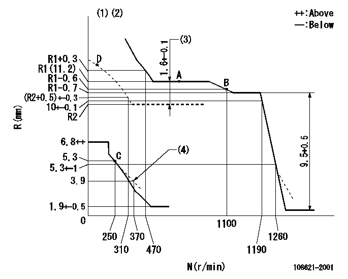
N:Pump speed
R:Rack position (mm)
(1)Tolerance for racks not indicated: +-0.05mm.
(2)Boost compensator cancel stroke: BSL
(3)Boost compensator stroke
(4)Damper spring setting
----------
BSL=1.8mm
----------
----------
BSL=1.8mm
----------
Speed control lever angle

F:Full speed
----------
----------
a=15.5deg+-5deg
----------
----------
a=15.5deg+-5deg
0000000901
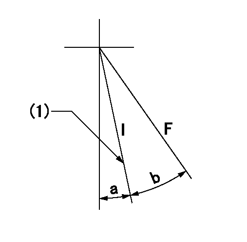
F:Full load
I:Idle
(1)Stopper bolt setting
----------
----------
a=8deg+-5deg b=34deg+-3deg
----------
----------
a=8deg+-5deg b=34deg+-3deg
Stop lever angle
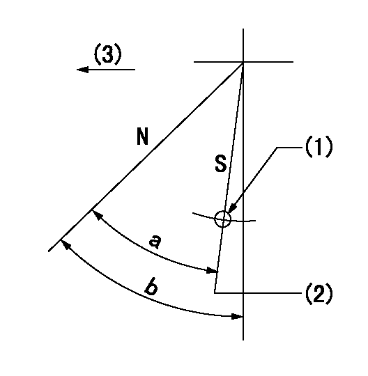
N:Pump normal
S:Stop the pump.
(1)R = aa
(2)Rack position bb
(3)Drive side
----------
aa=37mm bb=2.5-0.5mm
----------
a=41.5deg+7deg-5deg b=(59deg)+-5deg
----------
aa=37mm bb=2.5-0.5mm
----------
a=41.5deg+7deg-5deg b=(59deg)+-5deg
0000001301

(1)Pump vertical direction
(2)Coupling's key groove position at No 1 cylinder's beginning of injection
(3)Pre-stroke: aa
(4)-
----------
aa=5.6+-0.03mm
----------
a=(2deg)
----------
aa=5.6+-0.03mm
----------
a=(2deg)
0000002201 MICRO SWITCH
Adjustment of the micro-switch
Adjust the bolt to obtain the following lever position when the micro-switch is ON.
(1)Speed N1
(2)Rack position Ra
----------
N1=325r/min Ra=5.3+-0.1mm
----------
----------
N1=325r/min Ra=5.3+-0.1mm
----------
0000002301 RACK SENSOR

(VR) measurement voltage
(I) Part number of the control unit
(G) Apply red paint.
(H): End surface of the pump
1. Rack sensor adjustment (-0620)
(1)Fix the speed control lever at the full position
(2)Set the speed to N1 r/min.
(If the boost compensator is provided, apply boost pressure.)
(3)Adjust the bobbin (A) so that the rack sensor's output voltage is VR+-0.01.
(4)At that time, rack position must be Ra.
(5)Apply G at two places.
Connecting part between the joint (B) and the nut (F)
Connecting part between the joint (B) and the end surface of the pump (H)
----------
N1=700r/min Ra=R1(11.2)mm
----------
----------
N1=700r/min Ra=R1(11.2)mm
----------
Information:
Safety Section
Care must be taken to ensure that fluids are contained during performance of inspection, maintenance, testing, adjusting, and repair of the product. Be prepared to collect the fluid with suitable containers before opening any compartment or disassembling any component containing fluids.Refer to Special Publication, NENG2500, "Dealer Service Tool Catalog" for tools and supplies suitable to collect and contain fluids on Cat® products.Dispose of all fluids according to local regulations and mandates.
Illustration 1 g00104545Prevent the machine from movement. Park the machine on a level surface.Attach a "Do Not Operate" warning tag or a similar warning tag to the start switch or to the controls before you service the equipment. These warning tags (Special Instruction, SEHS7332) are available from your Caterpillar dealer.Required Parts
Table 1 contains the parts needed to complete the installation of the new DEF filter.Note: Only one DEF filter group is required per engine. Use Table 2 to determine which filter is the appropriate filter for each DEF header. Illustration 2 shows the location of the DEF header part number.
Table 1
Part Number Part Description Qty
378-3187 Diesel Exhaust Fluid Filter Gp 1
423-3251 Connector 1
391-5262 Gasket 1
425-0385 Filter As 1
452-6055 Filter Base As 1
453-1604(1) Diesel Exhaust Fluid Filter Gp 1
453-1605(1) Diesel Exhaust Fluid Filter Gp 1
453-1606(1) Diesel Exhaust Fluid Filter Gp 1
(1) Use Table 2 to choose the correct part that corresponds to the DEF header
Illustration 2 g03745839
(1) Location of DEF heater part number
Table 2
DEF Heater Part Number Required DEF Filter
434-3241 453-1604
434-3242 453-1605
434-3243 453-1606 Installation Procedure
Ensure that the area around the DEF heater is clean and free from debris.
Remove manifold DEF heater from DEF tank. Refer to Disassembly and Assembly, Manifold (DEF Heater) - Remove and Install for the correct procedure.
Illustration 3 g06013988
Typical example
Position filter base assembly (3) to DEF heater (2). Install screws (1) to filter base assembly (3). Tighten the self-tapping screws (1) securely.Note: Each half of the adapter has two small locking tabs that secure to the bottom side of the DEF heater.
Remove existing filter from the pickup pipe on manifold DEF heater. Refer to Disassembly and Assembly, Manifold (DEF Heater) - Remove and Install for the correct procedure.
Install a new filter to the pickup pipe on manifold DEF heater. Refer to Disassembly and Assembly, Manifold (DEF Heater) - Remove and Install for the correct procedure.
Illustration 4 g06013992
Typical example
Position the correct DEF filter (5) to the filter base assembly (3). Install band clamp (4). Tighten the band clamp to a torque
Have questions with 108621-2001?
Group cross 108621-2001 ZEXEL
108621-2001
INJECTION-PUMP ASSEMBLY