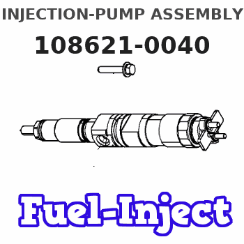
Information injection-pump assembly
ZEXEL
108621-0040
1086210040
Rating:
Cross reference number
ZEXEL
108621-0040
1086210040
Zexel num
Bosch num
Firm num
Name
108621-0040
INJECTION-PUMP ASSEMBLY
Calibration Data:
Adjustment conditions
Test oil
1404 Test oil ISO4113 or {SAEJ967d}
1404 Test oil ISO4113 or {SAEJ967d}
Test oil temperature
degC
40
40
45
Nozzle and nozzle holder
105780-8250
Bosch type code
1 688 901 101
Nozzle
105780-0120
Bosch type code
1 688 901 990
Nozzle holder
105780-2190
Opening pressure
MPa
20.7
Opening pressure
kgf/cm2
211
Injection pipe
Outer diameter - inner diameter - length (mm) mm 8-3-600
Outer diameter - inner diameter - length (mm) mm 8-3-600
Overflow valve
134424-4120
Overflow valve opening pressure
kPa
255
221
289
Overflow valve opening pressure
kgf/cm2
2.6
2.25
2.95
Tester oil delivery pressure
kPa
255
255
255
Tester oil delivery pressure
kgf/cm2
2.6
2.6
2.6
RED4 control unit part number
407915-0
590
RED4 rack sensor specifications
mm
19
PS/ACT control unit part no.
407980-2
24*
Digi switch no.
33
Direction of rotation (viewed from drive side)
Right R
Right R
Injection timing adjustment
Direction of rotation (viewed from drive side)
Right R
Right R
Injection order
1-4-2-6-
3-5
Pre-stroke
mm
6.4
6.37
6.43
Beginning of injection position
Drive side NO.1
Drive side NO.1
Difference between angles 1
Cal 1-4 deg. 60 59.75 60.25
Cal 1-4 deg. 60 59.75 60.25
Difference between angles 2
Cyl.1-2 deg. 120 119.75 120.25
Cyl.1-2 deg. 120 119.75 120.25
Difference between angles 3
Cal 1-6 deg. 180 179.75 180.25
Cal 1-6 deg. 180 179.75 180.25
Difference between angles 4
Cal 1-3 deg. 240 239.75 240.25
Cal 1-3 deg. 240 239.75 240.25
Difference between angles 5
Cal 1-5 deg. 300 299.75 300.25
Cal 1-5 deg. 300 299.75 300.25
Injection quantity adjustment
Rack position
(15.2)
PWM
%
73.6
Pump speed
r/min
650
650
650
Average injection quantity
mm3/st.
170
168
172
Max. variation between cylinders
%
0
-4
4
Basic
*
PS407980-224*
V
2.2+-0.0
1
PS407980-224*
mm
4+-0.05
Injection quantity adjustment_02
Rack position
(7.4)
PWM
%
29.9+-2.
8
Pump speed
r/min
295
295
295
Average injection quantity
mm3/st.
16.6
15.6
17.6
Max. variation between cylinders
%
0
-10
10
PS407980-224*
V
V1+0.05+
-0.01
PS407980-224*
mm
6.3+-0.0
3
Remarks
Refer to items regarding the pre-stroke actuator
Refer to items regarding the pre-stroke actuator
Governor adjustment
Pump speed
r/min
950--
Advance angle
deg.
0
0
0
Remarks
Start
Start
Governor adjustment_02
Pump speed
r/min
900
Advance angle
deg.
0.5
Governor adjustment_03
Pump speed
r/min
1000
Advance angle
deg.
1.5
1
2
Remarks
Finish
Finish
0000001201
Pre-stroke
mm
6.4
6.37
6.43
Remarks
When the timing sleeve is pushed up
When the timing sleeve is pushed up
_02
Connector angle
deg.
11.5
11
12
Remarks
When the eccentric pin is tightened
When the eccentric pin is tightened
_03
Supply voltage
V
24
23.5
24.5
Ambient temperature
degC
23
18
28
Pre-stroke
mm
2.4
2.35
2.45
Output voltage
V
2.95
2.94
2.96
Adjustment
*
_04
Supply voltage
V
24
23.5
24.5
Ambient temperature
degC
23
18
28
Pre-stroke
mm
6.4
6.37
6.43
Output voltage
V
1.2
1
1.4
Confirmation
*
Remarks
Output voltage V1
Output voltage V1
_05
Supply voltage
V
24
23.5
24.5
Ambient temperature
degC
23
18
28
Output voltage
V
3.05
3.05
Confirmation of operating range
*
Test data Ex:
Speed control lever angle
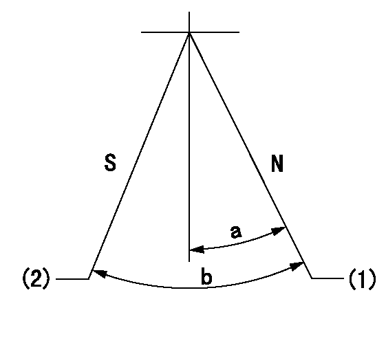
N:Pump normal
S:Stop the pump.
(1)Rack position = aa
(2)Rack position bb
----------
aa=20mm bb=1mm
----------
a=20deg+-5deg b=37deg+-5deg
----------
aa=20mm bb=1mm
----------
a=20deg+-5deg b=37deg+-5deg
0000000901

(1)Pump vertical direction
(2)Coupling's key groove position at No 1 cylinder's beginning of injection
(3)Pre-stroke: aa
(4)-
----------
aa=6.4+-0.03mm
----------
a=(20deg)
----------
aa=6.4+-0.03mm
----------
a=(20deg)
0000001501

A:Sealing position
B:Pre-stroke actuator
1. When installing the pre-stroke actuator on the pump, first tighten the installation bolts loosely, then move the actuator fully counterclockwise (viewed from the drive side).
Temporary tightening torque: 1 - 1.5 N.m (0.1 - 0.15 kgf.m)
2. Move the actuator in the clockwise direction when viewed from the drive side, and adjust so that it becomes the adjustment point of the adjustment value. Then tighten it.
Tightening torque: 7^9 N.m (0.7^0.9 kgf.m)
3. After prestroke actuator installation adjustment, simultaneously stamp both the actuator side and housing side.
----------
----------
----------
----------
0000001701

(PWM) Pulse width modulation (%)
(R) Rack position (mm)
Rack sensor output characteristics
1. Rack limit adjustment
(1)Measure the rack position R2 for PWM a2%.
(2)Confirm that it is within the range R2 = 15+-1 mm.
(3)Measure the rack position R1 at PWM a %.
(4)Confirm that it is within the range R2 - R1 = 10+-0.1 mm.
2. Check the limp home operation.
(1)Move the switch box's limp home switch to the limp home side.
(2)Confirm rack position L1 (mm ) and L2 (mm) for PWM in the above table.
3. Check the pull down operation.
(1)Confirm that the rack position is 19 mm at PWM B%.
(2)In the conditions described in the above table, move the switch box's pull down switch to the pull down side and confirm that the rack position momentarily becomes 1 mm or less.
----------
a1=16.25% a2=72.5% L1=1--mm L2=19++mm A=5% B=95%
----------
----------
a1=16.25% a2=72.5% L1=1--mm L2=19++mm A=5% B=95%
----------
Information:
General Contamination Control Recommendations or Practices
Maintaining a low contamination level can reduce down time and can control the maintenance cost of the engine. The productive life as well as the reliability of components and fluid systems is often increased as a result of proper contamination control practices.The following are general guidelines for controlling contaminants.
Refer to the Recommendations for Fuel Systems in this chapter for recommended fuel cleanliness levels and guidelines.
Refer to the engine Operation and Maintenance Manual for the required maintenance for all engine fluids.
When you add oil to an engine, use engine oil filters of 12 microns absolute efficiency. Ensure that the oil temperature is 20° C (68° F) or higher.
Perform scheduled S O S Services Oil Analysis for contamination in order to maintain the recommended ISO cleanliness level of fill and machine fluids. Refer to the S O S Oil Analysis section in this Special Publication. The particle count analysis can be performed by your Cat dealer. Particle count can be conducted during the scheduled S O S Services Oil Analysis for the compartment. Extra oil samples are not required for the particle count sampling.
Use only coolants that are recommended by Cat for your machine. Follow the recommended maintenance procedure for the cooling system in the Operation and Maintenance Manual for your machine.
Maintain the engine air filters and air intake system to avoid unwanted contaminant ingression.
Follow contamination control practices for the shop area, component/machine disassembly areas, parts, shop tools, test setups, test areas, storage areas and waste collection areas. Keep components clean during inspection, assembly, testing, and filling engines with clean fluids. Good practices will enhance component life and reduce downtime associated with contaminants. Your Cat dealer can provide details on proper contamination processes and practices.
Follow contamination control practices for the workplace and for the worksite. Maintaining clean oil fill fluids saves time and effort and ensures that fill fluids are at the proper cleanliness levels.
Use properly designed and maintained bulk storage fluids tanks.
Protect the fluids storage tanks from dirt and water entry by using 4 µm or less absolute efficiency breathers with the ability to remove water.
Keep the areas around the tanks filler necks clean of debris and water.
Drain the storage tanks from water and sediments frequently. The draining schedule depends on use of proper inlet and outlet filters, the use of 4 µm breathers with the ability to remove water, and following recommended contamination control practices. Based on the contamination control program followed, and/or on the fuel supplier recommendations, the storage tank draining schedule may be as frequent as daily until no water is present, and then can be extended to longer periods.
Install and maintain a properly designed and grounded filtration system. Filtration should include at the entry and at the dispensing point. Continuous bulk filtration may be required to ensure that dispensed oils meet the cleanliness target.
Cover, protect, and ensure cleanliness of all connection hoses, fittings, and dispensing nozzles.Note: Bulk fuel filtration units are available through your Cat dealer. Proper maintenance practices of
Have questions with 108621-0040?
Group cross 108621-0040 ZEXEL
Nissan-Diesel
Nissan-Diesel
Nissan-Diesel
Nissan-Diesel
Nissan-Diesel
Nissan-Diesel
108621-0040
INJECTION-PUMP ASSEMBLY