Information injection-pump assembly
ZEXEL
108621-0030
1086210030

Rating:
Cross reference number
ZEXEL
108621-0030
1086210030
Zexel num
Bosch num
Firm num
Name
108621-0030
INJECTION-PUMP ASSEMBLY
Calibration Data:
Adjustment conditions
Test oil
1404 Test oil ISO4113 or {SAEJ967d}
1404 Test oil ISO4113 or {SAEJ967d}
Test oil temperature
degC
40
40
45
Nozzle and nozzle holder
105780-8250
Bosch type code
1 688 901 101
Nozzle
105780-0120
Bosch type code
1 688 901 990
Nozzle holder
105780-2190
Opening pressure
MPa
20.7
Opening pressure
kgf/cm2
211
Injection pipe
Outer diameter - inner diameter - length (mm) mm 8-3-600
Outer diameter - inner diameter - length (mm) mm 8-3-600
Overflow valve
134424-4120
Overflow valve opening pressure
kPa
255
221
289
Overflow valve opening pressure
kgf/cm2
2.6
2.25
2.95
Tester oil delivery pressure
kPa
255
255
255
Tester oil delivery pressure
kgf/cm2
2.6
2.6
2.6
RED4 control unit part number
407915-0
590
RED4 rack sensor specifications
mm
19
PS/ACT control unit part no.
407980-2
24*
Digi switch no.
33
Direction of rotation (viewed from drive side)
Right R
Right R
Injection timing adjustment
Direction of rotation (viewed from drive side)
Right R
Right R
Injection order
1-4-2-6-
3-5
Pre-stroke
mm
6.4
6.37
6.43
Beginning of injection position
Drive side NO.1
Drive side NO.1
Difference between angles 1
Cal 1-4 deg. 60 59.75 60.25
Cal 1-4 deg. 60 59.75 60.25
Difference between angles 2
Cyl.1-2 deg. 120 119.75 120.25
Cyl.1-2 deg. 120 119.75 120.25
Difference between angles 3
Cal 1-6 deg. 180 179.75 180.25
Cal 1-6 deg. 180 179.75 180.25
Difference between angles 4
Cal 1-3 deg. 240 239.75 240.25
Cal 1-3 deg. 240 239.75 240.25
Difference between angles 5
Cal 1-5 deg. 300 299.75 300.25
Cal 1-5 deg. 300 299.75 300.25
Injection quantity adjustment
Rack position
(15.2)
PWM
%
73.6
Pump speed
r/min
650
650
650
Average injection quantity
mm3/st.
170
168
172
Max. variation between cylinders
%
0
-4
4
Basic
*
PS407980-224*
V
2.2+-0.0
1
PS407980-224*
mm
4+-0.05
Injection quantity adjustment_02
Rack position
(7.4)
PWM
%
29.9+-2.
8
Pump speed
r/min
295
295
295
Average injection quantity
mm3/st.
16.6
15.6
17.6
Max. variation between cylinders
%
0
-10
10
PS407980-224*
V
V1+0.05+
-0.01
PS407980-224*
mm
6.3+-0.0
3
Remarks
Refer to items regarding the pre-stroke actuator
Refer to items regarding the pre-stroke actuator
Governor adjustment
Pump speed
r/min
950--
Advance angle
deg.
0
0
0
Remarks
Start
Start
Governor adjustment_02
Pump speed
r/min
900
Advance angle
deg.
0.5
Governor adjustment_03
Pump speed
r/min
1000
Advance angle
deg.
1.5
1
2
Remarks
Finish
Finish
0000001201
Pre-stroke
mm
6.4
6.37
6.43
Remarks
When the timing sleeve is pushed up
When the timing sleeve is pushed up
_02
Connector angle
deg.
11.5
11
12
Remarks
When the eccentric pin is tightened
When the eccentric pin is tightened
_03
Supply voltage
V
24
23.5
24.5
Ambient temperature
degC
23
18
28
Pre-stroke
mm
2.4
2.35
2.45
Output voltage
V
2.95
2.94
2.96
Adjustment
*
_04
Supply voltage
V
24
23.5
24.5
Ambient temperature
degC
23
18
28
Pre-stroke
mm
6.4
6.37
6.43
Output voltage
V
1.2
1
1.4
Confirmation
*
Remarks
Output voltage V1
Output voltage V1
_05
Supply voltage
V
24
23.5
24.5
Ambient temperature
degC
23
18
28
Output voltage
V
3.05
3.05
Confirmation of operating range
*
Test data Ex:
Speed control lever angle
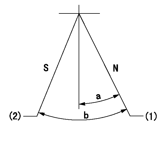
N:Pump normal
S:Stop the pump.
(1)Rack position = aa
(2)Rack position bb
----------
aa=20mm bb=1mm
----------
a=20deg+-5deg b=37deg+-5deg
----------
aa=20mm bb=1mm
----------
a=20deg+-5deg b=37deg+-5deg
0000000901

(1)Pump vertical direction
(2)Coupling's key groove position at No 1 cylinder's beginning of injection
(3)Pre-stroke: aa
(4)-
----------
aa=6.4+-0.03mm
----------
a=(20deg)
----------
aa=6.4+-0.03mm
----------
a=(20deg)
0000001501

A:Sealing position
B:Pre-stroke actuator
1. When installing the pre-stroke actuator on the pump, first tighten the installation bolts loosely, then move the actuator fully counterclockwise (viewed from the drive side).
Temporary tightening torque: 1 - 1.5 N.m (0.1 - 0.15 kgf.m)
2. Move the actuator in the clockwise direction when viewed from the drive side, and adjust so that it becomes the adjustment point of the adjustment value. Then tighten it.
Tightening torque: 7^9 N.m (0.7^0.9 kgf.m)
3. After prestroke actuator installation adjustment, simultaneously stamp both the actuator side and housing side.
----------
----------
----------
----------
0000001701

(PWM) Pulse width modulation (%)
(R) Rack position (mm)
Rack sensor output characteristics
1. Rack limit adjustment
(1)Measure the rack position R2 for PWM a2%.
(2)Confirm that it is within the range R2 = 15+-1 mm.
(3)Measure the rack position R1 at PWM a %.
(4)Confirm that it is within the range R2 - R1 = 10+-0.1 mm.
2. Check the limp home operation.
(1)Move the switch box's limp home switch to the limp home side.
(2)Confirm rack position L1 (mm ) and L2 (mm) for PWM in the above table.
3. Check the pull down operation.
(1)Confirm that the rack position is 19 mm at PWM B%.
(2)In the conditions described in the above table, move the switch box's pull down switch to the pull down side and confirm that the rack position momentarily becomes 1 mm or less.
----------
a1=16.25% a2=72.5% L1=1--mm L2=19++mm A=5% B=95%
----------
----------
a1=16.25% a2=72.5% L1=1--mm L2=19++mm A=5% B=95%
----------
Information:
Introduction
The problem that is identified below does not have a known permanent solution. Until a permanent solution is known, use the solution that is identified below.Problem
There have been some instances of the following active diagnostic codes:
651-6 Engine Injector Cylinder #01 : Current Above Normal
652-6 Engine Injector Cylinder #02 : Current Above Normal
653-6 Engine Injector Cylinder #03 : Current Above Normal
654-6 Engine Injector Cylinder #04 : Current Above NormalThe engine will be derated and will be difficult to start.Solution
Follow the correct troubleshooting procedure for the active diagnostic codes. Refer to Troubleshooting, Injector Solenoid - Test.
If the troubleshooting procedure identifies suspect injectors, use the electronic service tool to generate a Product Status Report (PSR). Select the "Histogram" option when generating the PSR.
Install replacement 418-3229 Fuel Injector Gp, as required. Refer to Disassembly and Assembly, Electronic Unit Injector - Remove and Disassembly and Assembly, Electronic Unit Injector - Install.
Use 169-7372 Fluid Sampling Bottles to obtain a fuel sample from the following locations:
Machine fuel tank ( 355 mL (12 oz)
Bulk fuel supply tank ( 355 mL (12 oz)Analyze the fuel sample. The fuel samples will need to be analyzed for the following properties:
Lubricity Wear Scar - "ASTM D6079" or "ISO 12156"
Density at 15° C (59° F) - "ASTM D1298", "ASTM D4052", "ISO 3675", or "ISO 12185"
Kinematic Viscosity at 40° C (104° F) - "ASTM D445", "ISO 3448", or "ISO 3104"
Sulfur - "ASTM D4294", "ASTM D5185", "ASTM D5453", "ASTM D26222", "ISO 20846", or "ISO 20884"
Water by Distillation - "ASTM D95", "ASTM D6304", "ASTM D2709", "ASTM D1796", or "ISO3734"
Cloud Point - "ASTM D2500" or "ISO 3015"
FAME - "EN 14078", "ASTM D7806", or "ASTM D7371"
Oxidation Stability - "EN 14112"
Copper - "ASTM D7111"
Sodium - "ASTM D7111"
Zinc - "ASTM D7111"
Calcium - "ASTM D7111"
Potassium - "ASTM D7111"Provide the results of the fuel sample.
Retain any removed injectors. The injectors will be requested for return through the "Send It Back" (SIB) process.
Submit the PSR along with TIB Media number, M0085259, and CPI number 386169 through "CPI Feedback" within the Service Information Management System (SIMSi).
Have questions with 108621-0030?
Group cross 108621-0030 ZEXEL
Nissan-Diesel
Nissan-Diesel
Nissan-Diesel
Nissan-Diesel
Nissan-Diesel
108621-0030
INJECTION-PUMP ASSEMBLY