Information injection-pump assembly
ZEXEL
107692-5230
1076925230

Rating:
Cross reference number
ZEXEL
107692-5230
1076925230
Zexel num
Bosch num
Firm num
Name
107692-5230
INJECTION-PUMP ASSEMBLY
14CG TICS MD-TI6 TICS
14CG TICS MD-TI6 TICS
Calibration Data:
Adjustment conditions
Test oil
1404 Test oil ISO4113 or {SAEJ967d}
1404 Test oil ISO4113 or {SAEJ967d}
Test oil temperature
degC
40
40
45
Nozzle and nozzle holder
105780-8250
Bosch type code
1 688 901 101
Nozzle
105780-0120
Bosch type code
1 688 901 990
Nozzle holder
105780-2190
Opening pressure
MPa
20.7
Opening pressure
kgf/cm2
211
Injection pipe
Outer diameter - inner diameter - length (mm) mm 8-3-600
Outer diameter - inner diameter - length (mm) mm 8-3-600
Overflow valve
131425-0520
Overflow valve opening pressure
kPa
255
221
289
Overflow valve opening pressure
kgf/cm2
2.6
2.25
2.95
Tester oil delivery pressure
kPa
255
255
255
Tester oil delivery pressure
kgf/cm2
2.6
2.6
2.6
PS/ACT control unit part no.
407910-3
03*
Selector switch no.
01
PS/ACT control unit part no.
407980-2
24*
Digi switch no.
15
Direction of rotation (viewed from drive side)
Right R
Right R
Injection timing adjustment
Direction of rotation (viewed from drive side)
Right R
Right R
Injection order
1-4-2-6-
3-5
Pre-stroke
mm
5.1
5.07
5.13
Beginning of injection position
Drive side NO.1
Drive side NO.1
Difference between angles 1
Cal 1-4 deg. 60 59.75 60.25
Cal 1-4 deg. 60 59.75 60.25
Difference between angles 2
Cyl.1-2 deg. 120 119.75 120.25
Cyl.1-2 deg. 120 119.75 120.25
Difference between angles 3
Cal 1-6 deg. 180 179.75 180.25
Cal 1-6 deg. 180 179.75 180.25
Difference between angles 4
Cal 1-3 deg. 240 239.75 240.25
Cal 1-3 deg. 240 239.75 240.25
Difference between angles 5
Cal 1-5 deg. 300 299.75 300.25
Cal 1-5 deg. 300 299.75 300.25
Injection quantity adjustment
Adjusting point
-
Rack position
14.4
Pump speed
r/min
1300
1300
1300
Average injection quantity
mm3/st.
113
111
115
Max. variation between cylinders
%
0
-4
4
Basic
*
Fixing the rack
*
PS407980-224*
V
2.25+-0.
01
PS407980-224*
mm
3.1+-0.0
5
PS407910-303*
V
2.25+-0.
01
PS407910-303*
mm
3.1+-0.0
5
Standard for adjustment of the maximum variation between cylinders
*
Injection quantity adjustment_02
Adjusting point
Z
Rack position
8.4+-0.5
Pump speed
r/min
465
465
465
Average injection quantity
mm3/st.
22.5
20.7
24.3
Max. variation between cylinders
%
0
-10
10
Fixing the rack
*
PS407980-224*
V
V1+0.05+
-0.01
PS407980-224*
mm
5+-0.03
PS407910-303*
V
V1+0.05+
-0.01
PS407910-303*
mm
5+-0.03
Standard for adjustment of the maximum variation between cylinders
*
Remarks
Refer to items regarding the pre-stroke actuator
Refer to items regarding the pre-stroke actuator
Injection quantity adjustment_03
Adjusting point
A
Rack position
R1(14.4)
Pump speed
r/min
1300
1300
1300
Average injection quantity
mm3/st.
113
112
114
Basic
*
Fixing the lever
*
Boost pressure
kPa
28
28
Boost pressure
mmHg
210
210
PS407980-224*
V
2.25+-0.
01
PS407980-224*
mm
3.1+-0.0
5
PS407910-303*
V
2.25+-0.
01
PS407910-303*
mm
3.1+-0.0
5
Injection quantity adjustment_04
Adjusting point
B
Rack position
R1-2.05
Pump speed
r/min
800
800
800
Average injection quantity
mm3/st.
103.5
99.5
107.5
Fixing the lever
*
Boost pressure
kPa
28
28
Boost pressure
mmHg
210
210
PS407980-224*
V
2.25+-0.
01
PS407980-224*
mm
3.1+-0.0
5
PS407910-303*
V
2.25+-0.
01
PS407910-303*
mm
3.1+-0.0
5
Injection quantity adjustment_05
Adjusting point
C
Rack position
(R2-0.5)
Pump speed
r/min
350
350
350
Average injection quantity
mm3/st.
47.4
45.4
49.4
Fixing the lever
*
Boost pressure
kPa
0
0
0
Boost pressure
mmHg
0
0
0
PS407980-224*
V
2.25+-0.
01
PS407980-224*
mm
3.1+-0.0
5
PS407910-303*
V
2.25+-0.
01
PS407910-303*
mm
3.1+-0.0
5
Boost compensator adjustment
Pump speed
r/min
350
350
350
Rack position
(R2-0.5)
Boost pressure
kPa
6.7
5.4
8
Boost pressure
mmHg
50
40
60
Boost compensator adjustment_02
Pump speed
r/min
350
350
350
Rack position
R2(R1-3.
95)
Boost pressure
kPa
14.7
14.7
14.7
Boost pressure
mmHg
110
110
110
0000001601
CU407980-224*
*
Actuator retarding type
*
Supply voltage
V
12
11.5
12.5
Ambient temperature
degC
23
18
28
Pre-stroke
mm
2
1.95
2.05
Output voltage
V
2.83
2.82
2.84
Adjustment
*
_02
CU407980-224*
*
Supply voltage
V
12
11.5
12.5
Ambient temperature
degC
23
18
28
Pre-stroke
mm
5.1
5.07
5.13
Output voltage
V
1.2
1
1.4
Confirmation
*
Remarks
Output voltage V1
Output voltage V1
_03
CU407980-224*
*
Supply voltage
V
12
11.5
12.5
Ambient temperature
degC
23
18
28
Output voltage
V
3.05
3.05
Confirmation of operating range
*
_04
CU407910-303*
*
Actuator retarding type
*
Supply voltage
V
12
11.5
12.5
Ambient temperature
degC
23
18
28
Pre-stroke
mm
2
1.95
2.05
Output voltage
V
2.83
2.82
2.84
Adjustment
*
_05
CU407910-303*
*
Supply voltage
V
12
11.5
12.5
Ambient temperature
degC
23
18
28
Pre-stroke
mm
5.1
5.07
5.13
Output voltage
V
1.2
1
1.4
Confirmation
*
Remarks
Output voltage V1
Output voltage V1
_06
CU407910-303*
*
Supply voltage
V
12
11.5
12.5
Ambient temperature
degC
23
18
28
Output voltage
V
3.05
3.05
Confirmation of operating range
*
Test data Ex:
Governor adjustment
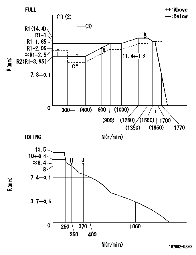
N:Pump speed
R:Rack position (mm)
(1)Torque cam stamping: T1
(2)Tolerance for racks not indicated: +-0.05mm.
(3)Boost compensator stroke: BCL
----------
T1=AF93 BCL=(0.5)+-0.1mm
----------
----------
T1=AF93 BCL=(0.5)+-0.1mm
----------
Speed control lever angle

F:Full speed
I:Idle
(1)Use the hole at R = aa
(2)Stopper bolt set position 'H'
----------
aa=93.5mm
----------
a=17deg+-5deg b=(38deg)+-3deg
----------
aa=93.5mm
----------
a=17deg+-5deg b=(38deg)+-3deg
Stop lever angle
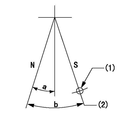
N:Pump normal
S:Stop the pump.
(1)Use the pin at R = aa
(2)Set the stopper bolt so that rack position = bb (speed = cc)
----------
aa=37mm bb=1.5+-0.3mm cc=0r/min
----------
a=20deg+-5deg b=45deg+-5deg
----------
aa=37mm bb=1.5+-0.3mm cc=0r/min
----------
a=20deg+-5deg b=45deg+-5deg
0000001301

(1)Pump vertical direction
(2)Coupling's key groove position at No 1 cylinder's beginning of injection
(3)Pre-stroke: aa
(4)-
----------
aa=5.1+-0.03mm
----------
a=(20deg)
----------
aa=5.1+-0.03mm
----------
a=(20deg)
0000001401
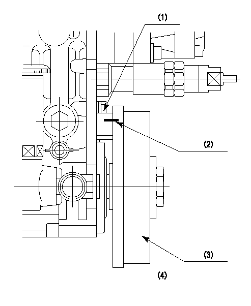
(1)Pointer
(2)Injection timing aligning mark
(3)Fly weight
(4)The actual shape and direction may be different from this illustration.
Operation sequence
1. Turn the prestroke actuator OFF.
2. Turn the camshaft as far as the No.1 cylinder's beginning of injection position.
3. Check that the pointer alignment mark of the injection pump and the alignment mark of the flywheel are matching.
4. If they are not matching, erase the alignment mark on the flywheel side, and stamp an alignment mark on the flywheel position that matches with the pointer side alignment mark.
5. Check again that the coupling's key groove position is in the No.1 cylinder's beginning of injection position.
----------
----------
----------
----------
0000001701
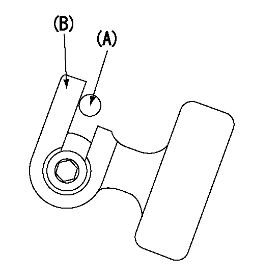
A : Stopper pin
B: Connector
----------
----------
----------
----------
0000001801
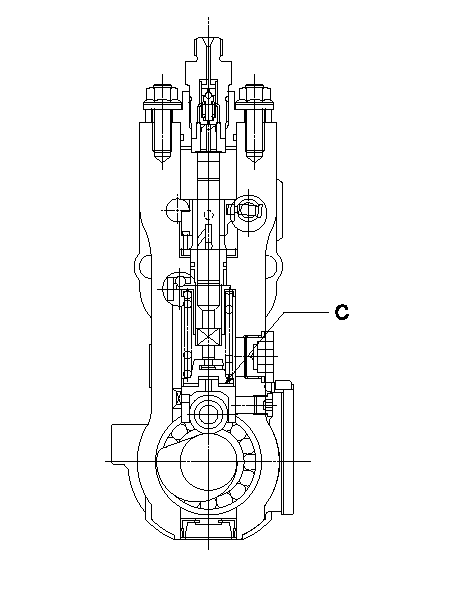
C:Shim
----------
----------
----------
----------
0000001901
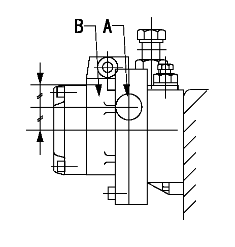
A:Sealing position
B:Pre-stroke actuator
1. When installing the pre-stroke actuator on the pump, first tighten the installation bolts loosely, then move the actuator fully counterclockwise (viewed from the drive side).
Temporary tightening torque: 1 - 1.5 N.m (0.1 - 0.15 kgf.m)
2. Move the actuator in the clockwise direction when viewed from the drive side, and adjust so that it becomes the adjustment point of the adjustment value. Then tighten it.
Tightening torque: 7^9 N.m (0.7^0.9 kgf.m)
3. After prestroke actuator installation adjustment, simultaneously stamp both the actuator side and housing side.
----------
----------
----------
----------
0000002201 RACK SENSOR
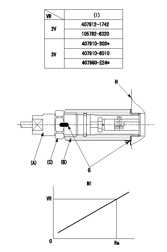
(VR) measurement voltage
(I) Part number of the control unit
(G) Apply red paint.
(H): End surface of the pump
1. Rack sensor adjustment (-0620)
(1)Fix the speed control lever at the full position
(2)Set the speed to N1 r/min.
(If the boost compensator is provided, apply boost pressure.)
(3)Adjust the bobbin (A) so that the rack sensor's output voltage is VR+-0.01.
(4)At that time, rack position must be Ra.
(5)Apply G at two places.
Connecting part between the joint (B) and the nut (F)
Connecting part between the joint (B) and the end surface of the pump (H)
----------
N1=1300r/min Ra=R1(14.4)mm
----------
----------
N1=1300r/min Ra=R1(14.4)mm
----------
0000002301 ACS
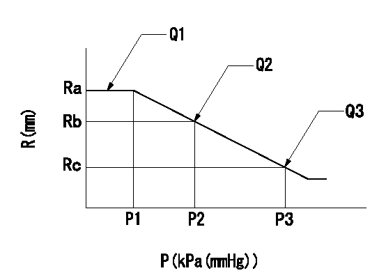
(P) Absolute pressure
(R) Rack position (mm)
1. Adjustment of the aneroid compensator
(1)Screw in the aneroid compensator body and attach the pushrod to the compensator lever so that the performance in the above graph can be obtained. The control lever must be at the full set position N = N1.
----------
N1=1300r/min
----------
Ra=R1(14.4)mm Rb=- Rc=(R1-0.75)mm P1=(80.6)+-2.7kPa((605)+-20mmHg) P2=- P3=57.7+-0.7kPa(433+-5mmHg) Q1=113+-1cm3/1000st Q2=- Q3=103+-2cm3/1000st
----------
N1=1300r/min
----------
Ra=R1(14.4)mm Rb=- Rc=(R1-0.75)mm P1=(80.6)+-2.7kPa((605)+-20mmHg) P2=- P3=57.7+-0.7kPa(433+-5mmHg) Q1=113+-1cm3/1000st Q2=- Q3=103+-2cm3/1000st
Information:
Caterpillar recommends that the coolant mixture contain a minimum of 30% Caterpillar Antifreeze (or equivalent) with 70% distilled or deionized water to maintain an adequate cavitation temperature for efficient water pump performance. Antifreeze concentration should be selected to provide protection to the lowest expected outside (ambient) temperature.Check the specific gravity of the antifreeze solution frequently in cold weather to ensure adequate freeze protection. Premix coolant solution to provide protection to the lowest expected outside (ambient) temperature. Pure undiluted antifreeze will freeze at -10°F (-23°C). Antifreeze concentrations above 60% antifreeze to 40% water are NOT recommended because the higher concentrations limit the ability of the coolant mixture to absorb supplemental coolant additive.
Use Caterpillar Antifreeze or any low silicate (ethylene or propylene glycol) antifreeze that meets ASTM D4985-89 (GM Specification 6038-M) requirements. Most commercial antifreezes are formulated for gasoline engine applications and have high silicate content. Caterpillar Antifreeze is formulated with a low silicate content and the proper coolant additives for heavy duty diesel engines.Caterpillar Antifreeze is available through your Caterpillar dealer in quantities that follow. Adding pure undiluted antifreeze as a makeup solution for cooling system top-off is an unacceptable practice. Add antifreeze premixed with acceptable water to the same freeze protection as your cooling system. Use the Antifreeze Concentration chart to assist in determining the concentration of Caterpillar Antifreeze to use. Check the coolant solution frequently in cold weather for glycol concentration with the 5P0957 or 5P3514 Coolant Tester (for Caterpillar products) to ensure adequate freeze protection. The testers are identical except temperature scales (°C or °F) and give immediate accurate readings for antifreeze/coolants that contain ethylene or propylene glycol. Both testers are available at your Caterpillar dealer.
If propylene glycol based antifreeze is used, DO NOT allow concentration greater than a 50/50 antifreeze to water mixture. The measurement of freeze protection must be made with a refractive-type tester (5P0957 or 5P3514) rather than the hydrometer-type tester commercially available. The hydrometer-type tester can be used to test ethylene glycol based antifreeze.
Supplemental Coolant Additive (Conditioner or Inhibitor)
The cooling system MUST contain supplemental coolant additives (conditioner or inhibitor) to control corrosion, cavitation and deposits. It is also necessary to prevent rust, scale, pitting and/or corrosion of engine parts contacted by coolant. The cooling system should be protected with a minimum of 3% concentration at all times, regardless of the concentration of antifreeze. Use supplemental coolant additive liquid OR an element (if equipped) to maintain a 3-6% concentration in the cooling system.
Never use antifreeze/water coolant only, in Caterpillar engines without supplemental coolant additive regardless of antifreeze concentration.Caterpillar or other manufacturer's products can be used as the supplemental coolant additive. DO NOT mix Caterpillar Supplemental Coolant Additive (Conditioner) liquid or elements with the other commercial products available; select a cooling system treatment and use it exclusively.Excessive concentration of supplemental coolant additive can form deposits which may cause engine damage, reduce the engine's heat transfer characteristics and could also accelerate water pump seal wear.
Use the 8T5296 Test Kit to check
Have questions with 107692-5230?
Group cross 107692-5230 ZEXEL
Nissan-Diesel
Nissan-Diesel
Nissan-Diesel
107692-5230
INJECTION-PUMP ASSEMBLY