Information injection-pump assembly
BOSCH
9 400 611 645
9400611645
ZEXEL
107692-5010
1076925010
Rating:
Service parts 107692-5010 INJECTION-PUMP ASSEMBLY:
1.
_
5.
AUTOM. ADVANCE MECHANIS
9.
_
11.
Nozzle and Holder
16600-Z5673
12.
Open Pre:MPa(Kqf/cm2)
19.6{200}
15.
NOZZLE SET
Include in #1:
107692-5010
as INJECTION-PUMP ASSEMBLY
Cross reference number
BOSCH
9 400 611 645
9400611645
ZEXEL
107692-5010
1076925010
Zexel num
Bosch num
Firm num
Name
Calibration Data:
Adjustment conditions
Test oil
1404 Test oil ISO4113 or {SAEJ967d}
1404 Test oil ISO4113 or {SAEJ967d}
Test oil temperature
degC
40
40
45
Nozzle and nozzle holder
105780-8250
Bosch type code
1 688 901 101
Nozzle
105780-0120
Bosch type code
1 688 901 990
Nozzle holder
105780-2190
Opening pressure
MPa
20.7
Opening pressure
kgf/cm2
211
Injection pipe
Outer diameter - inner diameter - length (mm) mm 8-3-600
Outer diameter - inner diameter - length (mm) mm 8-3-600
Overflow valve
131425-0520
Overflow valve opening pressure
kPa
255
221
289
Overflow valve opening pressure
kgf/cm2
2.6
2.25
2.95
Tester oil delivery pressure
kPa
255
255
255
Tester oil delivery pressure
kgf/cm2
2.6
2.6
2.6
PS/ACT control unit part no.
407910-3
03*
Selector switch no.
01
PS/ACT control unit part no.
407980-2
24*
Digi switch no.
15
Direction of rotation (viewed from drive side)
Right R
Right R
Injection timing adjustment
Direction of rotation (viewed from drive side)
Right R
Right R
Injection order
1-4-2-6-
3-5
Pre-stroke
mm
5.1
5.07
5.13
Beginning of injection position
Drive side NO.1
Drive side NO.1
Difference between angles 1
Cal 1-4 deg. 60 59.75 60.25
Cal 1-4 deg. 60 59.75 60.25
Difference between angles 2
Cyl.1-2 deg. 120 119.75 120.25
Cyl.1-2 deg. 120 119.75 120.25
Difference between angles 3
Cal 1-6 deg. 180 179.75 180.25
Cal 1-6 deg. 180 179.75 180.25
Difference between angles 4
Cal 1-3 deg. 240 239.75 240.25
Cal 1-3 deg. 240 239.75 240.25
Difference between angles 5
Cal 1-5 deg. 300 299.75 300.25
Cal 1-5 deg. 300 299.75 300.25
Injection quantity adjustment
Adjusting point
-
Rack position
14.4
Pump speed
r/min
1300
1300
1300
Average injection quantity
mm3/st.
113
111
115
Max. variation between cylinders
%
0
-4
4
Basic
*
Fixing the rack
*
PS407980-224*
V
2.25+-0.
01
PS407980-224*
mm
3.1+-0.0
5
PS407910-303*
V
2.25+-0.
01
PS407910-303*
mm
3.1+-0.0
5
Standard for adjustment of the maximum variation between cylinders
*
Injection quantity adjustment_02
Adjusting point
Z
Rack position
8.4+-0.5
Pump speed
r/min
465
465
465
Average injection quantity
mm3/st.
22.5
20.7
24.3
Max. variation between cylinders
%
0
-10
10
Fixing the rack
*
PS407980-224*
V
V1+0.05+
-0.01
PS407980-224*
mm
5+-0.03
PS407910-303*
V
V1+0.05+
-0.01
PS407910-303*
mm
5+-0.03
Standard for adjustment of the maximum variation between cylinders
*
Remarks
Refer to items regarding the pre-stroke actuator
Refer to items regarding the pre-stroke actuator
Injection quantity adjustment_03
Adjusting point
A
Rack position
R1(14.4)
Pump speed
r/min
1300
1300
1300
Average injection quantity
mm3/st.
113
112
114
Basic
*
Fixing the lever
*
Boost pressure
kPa
28
28
Boost pressure
mmHg
210
210
PS407980-224*
V
2.25+-0.
01
PS407980-224*
mm
3.1+-0.0
5
PS407910-303*
V
2.25+-0.
01
PS407910-303*
mm
3.1+-0.0
5
Injection quantity adjustment_04
Adjusting point
B
Rack position
R1-2.05
Pump speed
r/min
800
800
800
Average injection quantity
mm3/st.
103.5
99.5
107.5
Fixing the lever
*
Boost pressure
kPa
28
28
Boost pressure
mmHg
210
210
PS407980-224*
V
2.25+-0.
01
PS407980-224*
mm
3.1+-0.0
5
PS407910-303*
V
2.25+-0.
01
PS407910-303*
mm
3.1+-0.0
5
Injection quantity adjustment_05
Adjusting point
C
Rack position
(R2-0.5)
Pump speed
r/min
350
350
350
Average injection quantity
mm3/st.
47.4
45.4
49.4
Fixing the lever
*
Boost pressure
kPa
0
0
0
Boost pressure
mmHg
0
0
0
PS407980-224*
V
2.25+-0.
01
PS407980-224*
mm
3.1+-0.0
5
PS407910-303*
V
2.25+-0.
01
PS407910-303*
mm
3.1+-0.0
5
Boost compensator adjustment
Pump speed
r/min
350
350
350
Rack position
(R2-0.5)
Boost pressure
kPa
6.7
5.4
8
Boost pressure
mmHg
50
40
60
Boost compensator adjustment_02
Pump speed
r/min
350
350
350
Rack position
R2(R1-3.
95)
Boost pressure
kPa
14.7
14.7
14.7
Boost pressure
mmHg
110
110
110
0000001601
CU407980-224*
*
Actuator retarding type
*
Supply voltage
V
12
11.5
12.5
Ambient temperature
degC
23
18
28
Pre-stroke
mm
2
1.95
2.05
Output voltage
V
2.83
2.82
2.84
Adjustment
*
_02
CU407980-224*
*
Supply voltage
V
12
11.5
12.5
Ambient temperature
degC
23
18
28
Pre-stroke
mm
5.1
5.07
5.13
Output voltage
V
1.2
1
1.4
Confirmation
*
Remarks
Output voltage V1
Output voltage V1
_03
CU407980-224*
*
Supply voltage
V
12
11.5
12.5
Ambient temperature
degC
23
18
28
Output voltage
V
3.05
3.05
Confirmation of operating range
*
_04
CU407910-303*
*
Actuator retarding type
*
Supply voltage
V
12
11.5
12.5
Ambient temperature
degC
23
18
28
Pre-stroke
mm
2
1.95
2.05
Output voltage
V
2.83
2.82
2.84
Adjustment
*
_05
CU407910-303*
*
Supply voltage
V
12
11.5
12.5
Ambient temperature
degC
23
18
28
Pre-stroke
mm
5.1
5.07
5.13
Output voltage
V
1.2
1
1.4
Confirmation
*
Remarks
Output voltage V1
Output voltage V1
_06
CU407910-303*
*
Supply voltage
V
12
11.5
12.5
Ambient temperature
degC
23
18
28
Output voltage
V
3.05
3.05
Confirmation of operating range
*
Test data Ex:
Governor adjustment
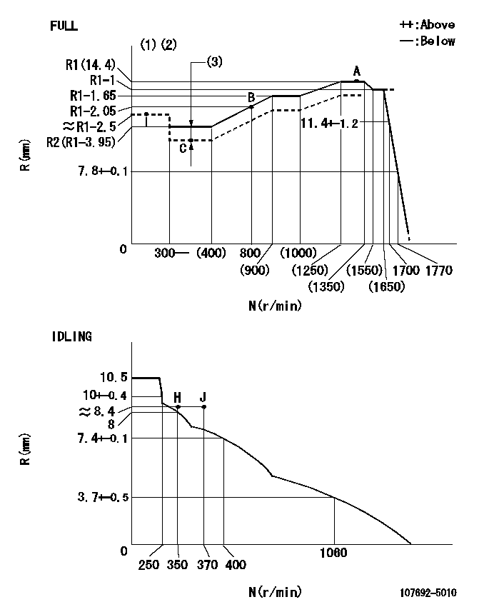
N:Pump speed
R:Rack position (mm)
(1)Torque cam stamping: T1
(2)Tolerance for racks not indicated: +-0.05mm.
(3)Boost compensator stroke: BCL
----------
T1=AF93 BCL=(0.5)+-0.1mm
----------
----------
T1=AF93 BCL=(0.5)+-0.1mm
----------
Speed control lever angle

F:Full speed
I:Idle
(1)Use the hole at R = aa
(2)Stopper bolt set position 'H'
----------
aa=93.5mm
----------
a=17deg+-5deg b=(38deg)+-3deg
----------
aa=93.5mm
----------
a=17deg+-5deg b=(38deg)+-3deg
Stop lever angle
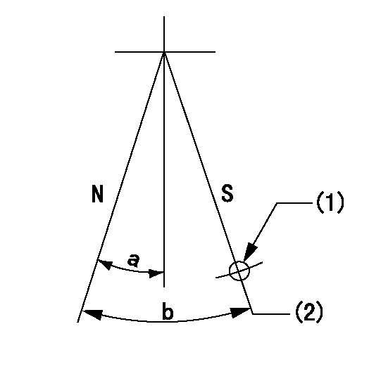
N:Pump normal
S:Stop the pump.
(1)Use the pin at R = aa
(2)Set the stopper bolt so that rack position = bb (speed = cc)
----------
aa=37mm bb=1.5+-0.3mm cc=0r/min
----------
a=20deg+-5deg b=45deg+-5deg
----------
aa=37mm bb=1.5+-0.3mm cc=0r/min
----------
a=20deg+-5deg b=45deg+-5deg
0000001301

(1)Pump vertical direction
(2)Coupling's key groove position at No 1 cylinder's beginning of injection
(3)Pre-stroke: aa
(4)-
----------
aa=5.1+-0.03mm
----------
a=(20deg)
----------
aa=5.1+-0.03mm
----------
a=(20deg)
0000001401
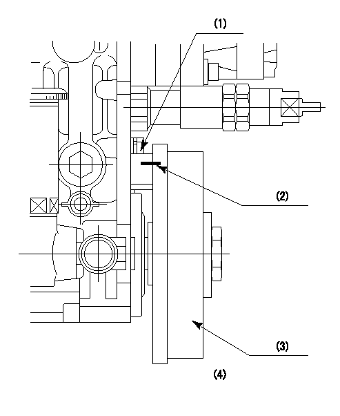
(1)Pointer
(2)Injection timing aligning mark
(3)Fly weight
(4)The actual shape and direction may be different from this illustration.
Operation sequence
1. Turn the prestroke actuator OFF.
2. Turn the camshaft as far as the No.1 cylinder's beginning of injection position.
3. Check that the pointer alignment mark of the injection pump and the alignment mark of the flywheel are matching.
4. If they are not matching, erase the alignment mark on the flywheel side, and stamp an alignment mark on the flywheel position that matches with the pointer side alignment mark.
5. Check again that the coupling's key groove position is in the No.1 cylinder's beginning of injection position.
----------
----------
----------
----------
0000001701
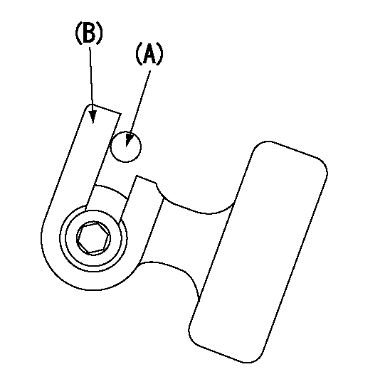
A : Stopper pin
B: Connector
----------
----------
----------
----------
0000001801
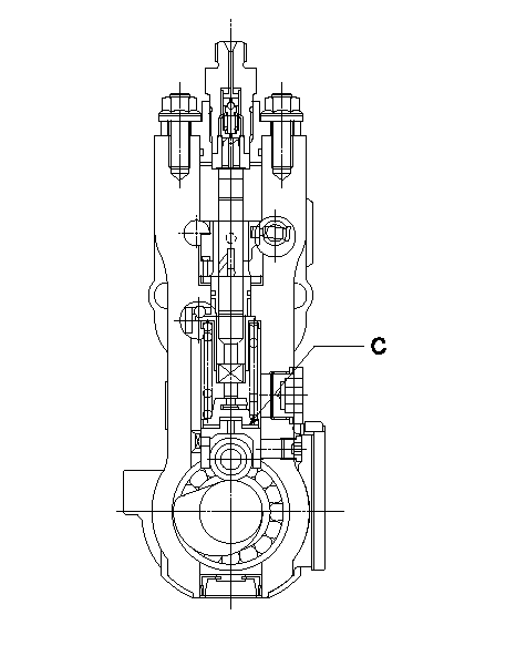
C:Shim
----------
----------
----------
----------
0000001901
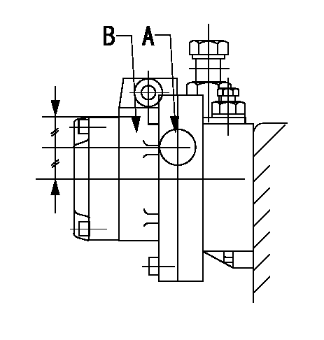
A:Sealing position
B:Pre-stroke actuator
1. When installing the pre-stroke actuator on the pump, first tighten the installation bolts loosely, then move the actuator fully counterclockwise (viewed from the drive side).
Temporary tightening torque: 1 - 1.5 N.m (0.1 - 0.15 kgf.m)
2. Move the actuator in the clockwise direction when viewed from the drive side, and adjust so that it becomes the adjustment point of the adjustment value. Then tighten it.
Tightening torque: 7^9 N.m (0.7^0.9 kgf.m)
3. After prestroke actuator installation adjustment, simultaneously stamp both the actuator side and housing side.
----------
----------
----------
----------
0000002201 RACK SENSOR
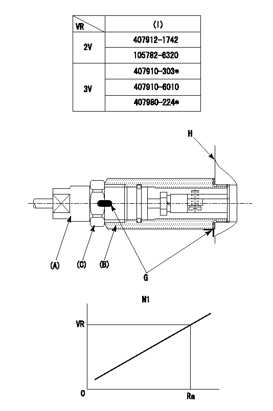
(VR) measurement voltage
(I) Part number of the control unit
(G) Apply red paint.
(H): End surface of the pump
1. Rack sensor adjustment (-0620)
(1)Fix the speed control lever at the full position
(2)Set the speed to N1 r/min.
(If the boost compensator is provided, apply boost pressure.)
(3)Adjust the bobbin (A) so that the rack sensor's output voltage is VR+-0.01.
(4)At that time, rack position must be Ra.
(5)Apply G at two places.
Connecting part between the joint (B) and the nut (F)
Connecting part between the joint (B) and the end surface of the pump (H)
----------
N1=1300r/min Ra=R1(14.4)mm
----------
----------
N1=1300r/min Ra=R1(14.4)mm
----------
0000002301 ACS
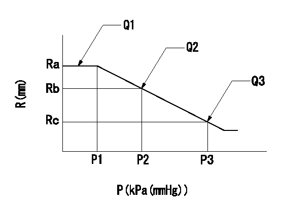
(P) Absolute pressure
(R) Rack position (mm)
1. Adjustment of the aneroid compensator
(1)Screw in the aneroid compensator body and attach the pushrod to the compensator lever so that the performance in the above graph can be obtained. The control lever must be at the full set position N = N1.
----------
N1=1300r/min
----------
Ra=R1(14.4)mm Rb=- Rc=(R1-0.75)mm P1=(80.6)+-2.7kPa((605)+-20mmHg) P2=- P3=57.7+-0.7kPa(433+-5mmHg) Q1=113+-1cm3/1000st Q2=- Q3=103+-2cm3/1000st
----------
N1=1300r/min
----------
Ra=R1(14.4)mm Rb=- Rc=(R1-0.75)mm P1=(80.6)+-2.7kPa((605)+-20mmHg) P2=- P3=57.7+-0.7kPa(433+-5mmHg) Q1=113+-1cm3/1000st Q2=- Q3=103+-2cm3/1000st
Information:
Fire Extinguisher
Have a fire extinguisher available and know how to use it. Inspect and have it serviced as recommended on its instruction plate.Crushing or Cutting Prevention
Support equipment and attachments properly when working beneath them.Never attempt adjustments while the engine is running unless otherwise specified in this manual.Stay clear of all rotating and moving parts. Guards should be in place whenever maintenance is not being performed.Keep objects away from moving fan blades. They will throw or cut any object or tool that falls or is pushed into them.Wear protective glasses when striking objects to avoid injury to your eyes.Chips or other debris can fly off objects when struck. Make sure no one can be injured by flying debris before striking any object.Mounting and Dismounting
Do not climb on, or jump off the engine or stand on components which cannot support your weight. Use an adequate ladder. Always use steps and handholds when mounting and dismounting.Clean steps, handholds and areas of the engine you will be working on or around.Before Starting the Engine
Inspect engine for potential hazards.Be sure all protective guards and covers are installed if an engine must be started to make adjustments or checks. To help prevent an accident caused by parts in rotation, work carefully around them.Do not disable or bypass automatic shutoff circuits. They are provided to prevent personal injury and engine damage.Never start an engine with the governor linkage disconnected.Make provisions for shutting off the air or fuel supply to stop the engine if there is an overspeed on start-up after performing repair or maintenance to the engine.See the Maintenance section of this manual for adjustment, or the Service Manual for repairs.Engine Starting
DO NOT start the engine or move any of the controls if there is a warning tag attached to the controls. Check with the person who attached the tag before starting.Make sure no one is working on, or close to the engine or engine driven components before starting it. Always make an inspection of the engine before and after starting.Start the engine only from the operator's station. Never short across the starter terminals or the batteries as this could bypass the engine neutral-start system as well as damage the electrical system.Always start the engine according to the required Engine Starting procedure described in this manual to prevent major engine component damage and personal injury.Make sure the engine is equipped with a lighting system as required by conditions.Make sure all lights are working properly.Check the jacket water and oil temperature gauges frequently during the operation of jacket water and/or lube oil heaters to ensure proper operation.Diesel engine exhaust contains products of combustion which may be harmful to your health. Always start and operate the engine in a well-ventilated area and, if in an enclosed area, vent the exhaust to the outside.Ether
Ether is poisonous and flammable.Inhaling ether vapors or repeated contact of ether with skin can cause personal injury.Do not smoke while changing ether cylinders.Use ether only in well ventilated areas.Use ether with care to avoid