Information injection-pump assembly
ZEXEL
107692-2290
1076922290
Rating:
Service parts 107692-2290 INJECTION-PUMP ASSEMBLY:
1.
_
5.
AUTOM. ADVANCE MECHANIS
7.
COUPLING PLATE
11.
Nozzle and Holder
ME075517
12.
Open Pre:MPa(Kqf/cm2)
21.6{220}
15.
NOZZLE SET
Include in #1:
107692-2290
as INJECTION-PUMP ASSEMBLY
Cross reference number
ZEXEL
107692-2290
1076922290
Zexel num
Bosch num
Firm num
Name
107692-2290
INJECTION-PUMP ASSEMBLY
Calibration Data:
Adjustment conditions
Test oil
1404 Test oil ISO4113 or {SAEJ967d}
1404 Test oil ISO4113 or {SAEJ967d}
Test oil temperature
degC
40
40
45
Nozzle and nozzle holder
105780-8250
Bosch type code
1 688 901 101
Nozzle
105780-0120
Bosch type code
1 688 901 990
Nozzle holder
105780-2190
Opening pressure
MPa
20.7
Opening pressure
kgf/cm2
211
Injection pipe
Outer diameter - inner diameter - length (mm) mm 8-3-600
Outer diameter - inner diameter - length (mm) mm 8-3-600
Overflow valve
131425-0520
Overflow valve opening pressure
kPa
255
221
289
Overflow valve opening pressure
kgf/cm2
2.6
2.25
2.95
Tester oil delivery pressure
kPa
255
255
255
Tester oil delivery pressure
kgf/cm2
2.6
2.6
2.6
RED3 control unit part number
407910-3
960
RED3 rack sensor specifications
mm
19
PS/ACT control unit part no.
407980-2
24*
Digi switch no.
17
Direction of rotation (viewed from drive side)
Left L
Left L
Injection timing adjustment
Direction of rotation (viewed from drive side)
Left L
Left L
Injection order
1-5-3-6-
2-4
Pre-stroke
mm
5.1
5.07
5.13
Beginning of injection position
Governor side NO.1
Governor side NO.1
Difference between angles 1
Cal 1-5 deg. 60 59.75 60.25
Cal 1-5 deg. 60 59.75 60.25
Difference between angles 2
Cal 1-3 deg. 120 119.75 120.25
Cal 1-3 deg. 120 119.75 120.25
Difference between angles 3
Cal 1-6 deg. 180 179.75 180.25
Cal 1-6 deg. 180 179.75 180.25
Difference between angles 4
Cyl.1-2 deg. 240 239.75 240.25
Cyl.1-2 deg. 240 239.75 240.25
Difference between angles 5
Cal 1-4 deg. 300 299.75 300.25
Cal 1-4 deg. 300 299.75 300.25
Injection quantity adjustment
Rack position
(12.5)
Vist
V
1.98
1.98
1.98
Pump speed
r/min
800
800
800
Average injection quantity
mm3/st.
140
139
141
Max. variation between cylinders
%
0
-3
3
Basic
*
PS407980-224*
V
2.25+-0.
01
PS407980-224*
mm
3.1+-0.0
5
Injection quantity adjustment_02
Rack position
(6.6)
Vist
V
2.9
2.8
3
Pump speed
r/min
410
410
410
Average injection quantity
mm3/st.
16.5
14.7
18.3
Max. variation between cylinders
%
0
-15
15
PS407980-224*
V
V1+0.05+
-0.01
PS407980-224*
mm
5+-0.03
Remarks
Refer to items regarding the pre-stroke actuator
Refer to items regarding the pre-stroke actuator
0000001201
CU407980-224*
*
Actuator retarding type
*
Supply voltage
V
24
23.5
24.5
Ambient temperature
degC
23
18
28
Pre-stroke
mm
2
1.95
2.05
Output voltage
V
2.83
2.82
2.84
Adjustment
*
_02
CU407980-224*
*
Supply voltage
V
24
23.5
24.5
Ambient temperature
degC
23
18
28
Pre-stroke
mm
5.1
5.07
5.13
Output voltage
V
1.2
1
1.4
Confirmation
*
Remarks
Output voltage V1
Output voltage V1
_03
CU407980-224*
*
Supply voltage
V
24
23.5
24.5
Ambient temperature
degC
23
18
28
Output voltage
V
3.05
3.05
Confirmation of operating range
*
Test data Ex:
Speed control lever angle
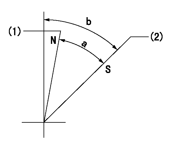
N:Pump normal
S:Stop the pump.
(1)Rack position = aa
(2)Rack position bb
----------
aa=1mm bb=20mm
----------
a=37deg+-5deg b=39deg+-5deg
----------
aa=1mm bb=20mm
----------
a=37deg+-5deg b=39deg+-5deg
0000000901
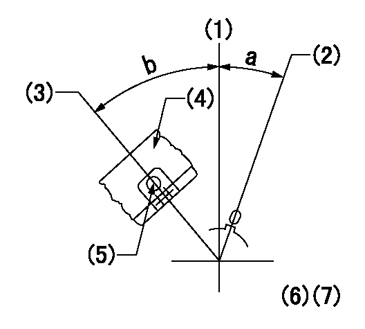
(1)Pump vertical direction
(2)Coupling's key groove position at No 1 cylinder's beginning of injection
(3)At the No 1 cylinder's beginning of injection position, stamp an aligning mark on the damper to align with the pointer's groove.
(4)Damper
(5)Pointer
(6)B.T.D.C.: aa
(7)Pre-stroke: bb
----------
aa=2deg bb=5.1+-0.03mm
----------
a=(2deg) b=(40deg)
----------
aa=2deg bb=5.1+-0.03mm
----------
a=(2deg) b=(40deg)
Stop lever angle

(1)Pointer
(2)Injection timing aligning mark
(3)Fly weight
(4)The actual shape and direction may be different from this illustration.
Operation sequence
1. Turn the prestroke actuator OFF.
2. Turn the camshaft as far as the No.1 cylinder's beginning of injection position.
3. Check that the pointer alignment mark of the injection pump and the alignment mark of the flywheel are matching.
4. If they are not matching, erase the alignment mark on the flywheel side, and stamp an alignment mark on the flywheel position that matches with the pointer side alignment mark.
5. Check again that the coupling's key groove position is in the No.1 cylinder's beginning of injection position.
----------
----------
----------
----------
0000001301

A : Stopper pin
B: Connector
----------
----------
----------
----------
0000001401

C:Shim
----------
----------
----------
----------
0000001501

A:Sealing position
B:Pre-stroke actuator
1. When installing the pre-stroke actuator on the pump, first tighten the installation bolts loosely, then move the actuator fully clockwise (viewed from the drive side).
Temporary tightening torque: 1 - 1.5 N.m (0.1 - 0.15 kgf.m)
2. Move the actuator in the counterclockwise direction when viewed from the drive side, and adjust so that it becomes the adjustment point of the adjustment value. Then tighten it.
Tightening torque: 7^9 N.m (0.7^0.9 kgf.m)
3. After prestroke actuator installation adjustment, simultaneously stamp both the actuator side and housing side.
----------
----------
----------
----------
0000001701

(Rs) rack sensor specifications
(C/U) control unit part number
(V) Rack sensor output voltage
(R) Rack position (mm)
1. Confirming governor output characteristics (rack 19 mm, span 6 mm)
(1)When the output voltages of the rack sensor are V1 and V2, check that the rack positions R1 and R2 in the table above are satisfied.
----------
----------
----------
----------
0000001901 RACK SENSOR

(VR) measurement voltage
(I) Part number of the control unit
(G) Apply red paint.
(H): End surface of the pump
1. Rack sensor adjustment (154610-0620)
(1)At governor side rack sensor output voltage V1, adjust the bobbin (A) so that the drive side rack sensor output voltage is VR+-0.01.
(2)Apply G at two places.
Connecting part between the joint (B) and the nut (F)
Connecting part between the joint (B) and the end surface of the pump (H)
----------
V1=1.6V
----------
----------
V1=1.6V
----------
Information:
Driver Techniques
The manner in which a vehicle is driven can have a dramatic effect on fuel consumption. Operators can maximize fuel economy and engine life by practicing the techniques of using minimum power and low engine rpm. The following tips can optimize fuel economy by making maximum use of the potential efficiency of the engine and vehicle.The 3176 can be programmed to ensure that the engine and vehicle are operated within specific limits for maximum fuel economy. (Refer to topic, Customer Specified Parameters, in this publication for information.)Caterpillar engines are designed to operate at lower engine rpm (speed) and have demonstrated excellent fuel savings and longer service life when operated in this manner.Starting Out
This truck engine does not require long warm-up times that waste fuel. Below 63°F (17°C), the 3176 system automatically idles at 1000 rpm. It takes just a few minutes in the summer and a bit longer in the winter to warm up the mechanical engine, and for the 3176 engine to reduce engine rpm to the programmed low idle rpm.A load can be applied to the engine after normal oil pressure is reached and the water temperature gauge begins to rise. To get the vehicle in motion, use a gear that will result in a smooth, easy start without increasing engine speed above low idle or slipping the clutch. Engage the clutch smoothly. Interrupted and jerky clutch engagement put stress on the drive train and wastes fuel.Keep engine rpm (speed) at a minimum. Use just enough rpm to pick up the next gear. This technique is called progressive shifting. It can improve fuel consumption and will not harm the engine.Progressive Shifting
Drive line efficiency is best in the low to mid rpm range (1100 to 1600 rpm) of the engine due to reduced frictional losses of the engine, transmission and rear axles. When accelerating under normal level road conditions, the engine should be operated in this most efficient rpm range by using only enough power to pick up the next higher gear. This technique of upshifting at the lowest possible rpm is called progressive shifting.Progressive shifting also reduces the time to accelerate to the desired vehicle speed. Top gear is reached sooner because engine rpm does not have to fall off as far to synchronize the gears of the transmission. The key to progressive shifting is to use minimum rpm, minimum power and upshift early while accelerating the truck.The 3176 can be programmed to limit engine acceleration above pre-programmed engine rpm settings. This feature encourages the operator to practice progressive shifting techniques.Refer to Driving Techniques for Maximum Fuel Economy, form LEDT5092 for more information.Cruising Speed
It's a simple fact that the faster a vehicle is driven, the more fuel it will consume. A few miles per hour (kilometers per hour) can make a significant difference in fuel economy.Increasing cruising speed from 55 to 65 mph (88 to 104 km/h) will increase fuel consumption of a typical class 8 truck approximately 1.0 mpg (0.4 km/L). A practice of
Have questions with 107692-2290?
Group cross 107692-2290 ZEXEL
Mitsubishi
Mitsubishi
107692-2290
INJECTION-PUMP ASSEMBLY