Information injection-pump assembly
ZEXEL
107692-2160
1076922160

Rating:
Cross reference number
ZEXEL
107692-2160
1076922160
Zexel num
Bosch num
Firm num
Name
107692-2160
INJECTION-PUMP ASSEMBLY
14CG TICS MD-TI6 TICS
14CG TICS MD-TI6 TICS
Calibration Data:
Adjustment conditions
Test oil
1404 Test oil ISO4113 or {SAEJ967d}
1404 Test oil ISO4113 or {SAEJ967d}
Test oil temperature
degC
40
40
45
Nozzle and nozzle holder
105780-8250
Bosch type code
1 688 901 101
Nozzle
105780-0120
Bosch type code
1 688 901 990
Nozzle holder
105780-2190
Opening pressure
MPa
20.7
Opening pressure
kgf/cm2
211
Injection pipe
Outer diameter - inner diameter - length (mm) mm 8-3-600
Outer diameter - inner diameter - length (mm) mm 8-3-600
Overflow valve
131424-8420
Overflow valve opening pressure
kPa
255
221
289
Overflow valve opening pressure
kgf/cm2
2.6
2.25
2.95
Tester oil delivery pressure
kPa
255
255
255
Tester oil delivery pressure
kgf/cm2
2.6
2.6
2.6
RED3 control unit part number
407910-2
470
RED3 rack sensor specifications
mm
15
PS/ACT control unit part no.
407980-2
24*
Digi switch no.
17
Direction of rotation (viewed from drive side)
Left L
Left L
Injection timing adjustment
Direction of rotation (viewed from drive side)
Left L
Left L
Injection order
1-5-3-6-
2-4
Pre-stroke
mm
5.6
5.57
5.63
Beginning of injection position
Governor side NO.1
Governor side NO.1
Difference between angles 1
Cal 1-5 deg. 60 59.75 60.25
Cal 1-5 deg. 60 59.75 60.25
Difference between angles 2
Cal 1-3 deg. 120 119.75 120.25
Cal 1-3 deg. 120 119.75 120.25
Difference between angles 3
Cal 1-6 deg. 180 179.75 180.25
Cal 1-6 deg. 180 179.75 180.25
Difference between angles 4
Cyl.1-2 deg. 240 239.75 240.25
Cyl.1-2 deg. 240 239.75 240.25
Difference between angles 5
Cal 1-4 deg. 300 299.75 300.25
Cal 1-4 deg. 300 299.75 300.25
Injection quantity adjustment
Rack position
(11)
Vist
V
1.8
1.8
1.8
Pump speed
r/min
700
700
700
Average injection quantity
mm3/st.
120.5
119.5
121.5
Max. variation between cylinders
%
0
-3
3
Basic
*
PS407980-224*
V
2.25+-0.
01
PS407980-224*
mm
3.6+-0.0
5
Injection quantity adjustment_02
Rack position
(6)
Vist
V
2.8
2.7
2.9
Pump speed
r/min
440
440
440
Average injection quantity
mm3/st.
15.5
13.7
17.3
Max. variation between cylinders
%
0
-15
15
PS407980-224*
V
V1+0.05+
-0.01
PS407980-224*
mm
5.5+-0.0
3
Remarks
Refer to items regarding the pre-stroke actuator
Refer to items regarding the pre-stroke actuator
0000001201
CU407980-224*
*
Actuator advancing type
*
Supply voltage
V
24
23.5
24.5
Ambient temperature
degC
23
18
28
Pre-stroke
mm
2.5
2.45
2.55
Output voltage
V
2.83
2.82
2.84
Adjustment
*
_02
CU407980-224*
*
Supply voltage
V
24
23.5
24.5
Ambient temperature
degC
23
18
28
Pre-stroke
mm
5.6
5.57
5.63
Output voltage
V
1.2
1
1.4
Confirmation
*
Remarks
Output voltage V1
Output voltage V1
_03
CU407980-224*
*
Supply voltage
V
24
23.5
24.5
Ambient temperature
degC
23
18
28
Output voltage
V
3.05
3.05
Confirmation of operating range
*
Test data Ex:
Speed control lever angle

N:Pump normal
S:Stop the pump.
(1)Rack position = aa
(2)Rack position bb
----------
aa=1mm bb=16mm
----------
a=31deg+-5deg b=29deg+-5deg
----------
aa=1mm bb=16mm
----------
a=31deg+-5deg b=29deg+-5deg
0000000901
(1)Pump vertical direction
(2)Coupling's key groove position at No 1 cylinder's beginning of injection
(3)At the No 1 cylinder's beginning of injection position, stamp an aligning mark on the damper to align with the pointer's groove.
(4)Damper
(5)Pointer
(6)B.T.D.C.: aa
(7)Pre-stroke: bb
----------
aa=2deg bb=5.6+-0.03mm
----------
a=(0deg) b=(40deg)
----------
aa=2deg bb=5.6+-0.03mm
----------
a=(0deg) b=(40deg)
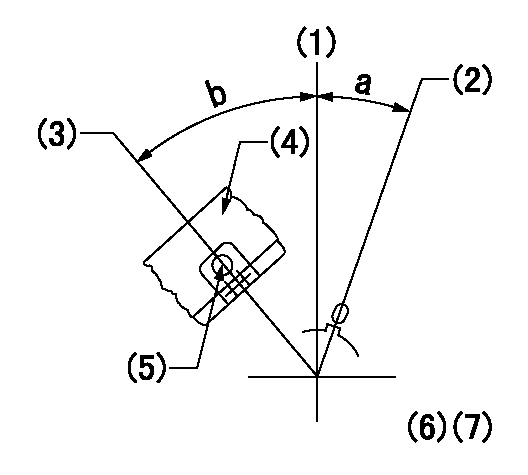
Stop lever angle

(1)Pointer
(2)Injection timing aligning mark
(3)Fly weight
(4)The actual shape and direction may be different from this illustration.
Operation sequence
1. Turn the prestroke actuator OFF.
2. Turn the camshaft as far as the No.1 cylinder's beginning of injection position.
3. Check that the pointer alignment mark of the injection pump and the alignment mark of the flywheel are matching.
4. If they are not matching, erase the alignment mark on the flywheel side, and stamp an alignment mark on the flywheel position that matches with the pointer side alignment mark.
5. Check again that the coupling's key groove position is in the No.1 cylinder's beginning of injection position.
----------
----------
----------
----------
0000001301
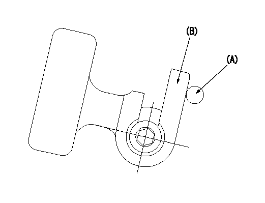
A : Stopper pin
B: Connector
----------
----------
----------
----------
0000001401

C:Shim
----------
----------
----------
----------
0000001501

A:Sealing position
B:Pre-stroke actuator
1. When installing the pre-stroke actuator on the pump, first tighten the installation bolts loosely, then move the actuator fully clockwise (viewed from the drive side).
Temporary tightening torque: 1 - 1.5 N.m (0.1 - 0.15 kgf.m)
2. Move the actuator in the counterclockwise direction when viewed from the drive side, and adjust so that it becomes the adjustment point of the adjustment value. Then tighten it.
Tightening torque: 7^9 N.m (0.7^0.9 kgf.m)
3. After prestroke actuator installation adjustment, simultaneously stamp both the actuator side and housing side.
----------
----------
----------
----------
0000001701

(Rs) rack sensor specifications
(C/U) control unit part number
(V) Rack sensor output voltage
(R) Rack position (mm)
1. Confirming governor output characteristics (rack 15 mm, span 6 mm)
(1)When the output voltages of the rack sensor are V1 and V2, check that the rack positions R1 and R2 in the table above are satisfied.
----------
----------
----------
----------
0000001901 RACK SENSOR

(VR) measurement voltage
(I) Part number of the control unit
(G) Apply red paint.
(H): End surface of the pump
1. Rack sensor adjustment (154610-0620)
(1)At governor side rack sensor output voltage V1, adjust the bobbin (A) so that the drive side rack sensor output voltage is VR+-0.01.
(2)Apply G at two places.
Connecting part between the joint (B) and the nut (F)
Connecting part between the joint (B) and the end surface of the pump (H)
----------
V1=1V
----------
----------
V1=1V
----------
Information:
Adjustment of the fuel system outside Caterpillar specified limits will not improve fuel efficiency and could result in damage to the engine.
If you feel you have a vehicle performance problem, first consider the impact of vehicle efficiency and operating characteristics (vehicle speed, design, etc.), on power demand before questioning engine performance.In the case of poor fuel economy, the engine is not likely to be the cause without the presence of excessive exhaust smoke and/or a significant loss of power.If you feel you have a valid engine performance problem, contact an authorized Caterpillar dealer for assistance. If your engine is under warranty, then the Caterpillar warranty or extended service coverage (if purchased) will cover the cost of resolving a valid engine performance deficiency. Refer to the Warranty Section in this publication and your Caterpillar dealer for details.However, if the engine is not found at fault, all costs incurred will be the responsibility of the owner.Performance Analysis Report (PAR)
PAR complements a good preventive maintenance program. PAR analysis can monitor the condition of your engine and to determine if your engine is operating at peak efficiency.PAR reflects the results of various tests normally conducted by your Caterpillar dealer for the purpose of:* confirming your engine is operating efficiently and within specification.* identifying potential problems.* determining components or systems that should be adjusted, replaced, etc.Approximately eighty to 85% of your truck engine's total operation and maintenance cost is the cost of fuel. Therefore, substantial cost reductions can be achieved by keeping your engine operating at peak efficiency. Fuel consumption and performance of your engine is affected by vehicle specifications, how it is operated and condition of the engine. Each plays an important part in minimizing your total owner and operating cost.Do not attempt to use PAR until the first engine oil change. This allows for sufficient break-in of the engine, drive train and tires. Fuel rate and turbocharger boost will be measured under load at five engine speeds and compared to factory specifications. Fuel rate and boost are the primary indicators of your engine's performance and the analysis of this data will help pinpoint potential problems faster.Wheel horsepower (kW) will also be recorded during the initial PAR test to establish your truck's exact wheel horsepower (kW) over its full operating range. This power can then be compared to the power of subsequent PAR tests. Power available at the wheels is not only the result of the condition of the engine, but also the transmission, drive axle(s), brakes, tires and engine drive accessories.Consult your Caterpillar dealer for complete information and assistance in establishing a PAR program for your engine.Refer to Form LEDT4211, PEDP0026 and/or Performance Troubleshooting Manual, Form SENR4249 or your Caterpillar dealer for more information on PAR.Contact your nearest Caterpillar dealer for information on PAR and the location of the nearest, approved dynamometer.
Have questions with 107692-2160?
Group cross 107692-2160 ZEXEL
107692-2160
INJECTION-PUMP ASSEMBLY