Information injection-pump assembly
BOSCH
F 019 Z10 763
f019z10763
ZEXEL
107692-1660
1076921660

Rating:
Service parts 107692-1660 INJECTION-PUMP ASSEMBLY:
1.
_
5.
AUTOM. ADVANCE MECHANIS
7.
COUPLING PLATE
11.
Nozzle and Holder
12.
Open Pre:MPa(Kqf/cm2)
18.1(185)/22.1(225)
14.
NOZZLE
Include in #1:
107692-1660
as INJECTION-PUMP ASSEMBLY
Cross reference number
BOSCH
F 019 Z10 763
f019z10763
ZEXEL
107692-1660
1076921660
Zexel num
Bosch num
Firm num
Name
Calibration Data:
Adjustment conditions
Test oil
1404 Test oil ISO4113 or {SAEJ967d}
1404 Test oil ISO4113 or {SAEJ967d}
Test oil temperature
degC
40
40
45
Nozzle and nozzle holder
105780-8250
Bosch type code
1 688 901 101
Nozzle
105780-0120
Bosch type code
1 688 901 990
Nozzle holder
105780-2190
Opening pressure
MPa
20.7
Opening pressure
kgf/cm2
211
Injection pipe
Outer diameter - inner diameter - length (mm) mm 8-3-600
Outer diameter - inner diameter - length (mm) mm 8-3-600
Overflow valve
131425-1820
Overflow valve opening pressure
kPa
255
221
289
Overflow valve opening pressure
kgf/cm2
2.6
2.25
2.95
Tester oil delivery pressure
kPa
255
255
255
Tester oil delivery pressure
kgf/cm2
2.6
2.6
2.6
PS/ACT control unit part no.
407980-2
24*
Digi switch no.
17
Direction of rotation (viewed from drive side)
Left L
Left L
Injection timing adjustment
Direction of rotation (viewed from drive side)
Left L
Left L
Injection order
1-5-3-6-
2-4
Pre-stroke
mm
5.1
5.07
5.13
Beginning of injection position
Governor side NO.1
Governor side NO.1
Difference between angles 1
Cal 1-5 deg. 60 59.75 60.25
Cal 1-5 deg. 60 59.75 60.25
Difference between angles 2
Cal 1-3 deg. 120 119.75 120.25
Cal 1-3 deg. 120 119.75 120.25
Difference between angles 3
Cal 1-6 deg. 180 179.75 180.25
Cal 1-6 deg. 180 179.75 180.25
Difference between angles 4
Cyl.1-2 deg. 240 239.75 240.25
Cyl.1-2 deg. 240 239.75 240.25
Difference between angles 5
Cal 1-4 deg. 300 299.75 300.25
Cal 1-4 deg. 300 299.75 300.25
Injection quantity adjustment
Adjusting point
-
Rack position
14.2
Pump speed
r/min
850
850
850
Average injection quantity
mm3/st.
114
112.4
115.6
Max. variation between cylinders
%
0
-2.5
2.5
Basic
*
Fixing the rack
*
PS407980-224*
V
2.25+-0.
01
PS407980-224*
mm
3.1+-0.0
5
Standard for adjustment of the maximum variation between cylinders
*
Injection quantity adjustment_02
Adjusting point
Z
Rack position
8.5+-0.5
Pump speed
r/min
435
435
435
Average injection quantity
mm3/st.
9
7.7
10.3
Max. variation between cylinders
%
0
-14
14
Fixing the rack
*
PS407980-224*
V
V1+0.05+
-0.01
PS407980-224*
mm
5+-0.03
Standard for adjustment of the maximum variation between cylinders
*
Remarks
Refer to items regarding the pre-stroke actuator
Refer to items regarding the pre-stroke actuator
Injection quantity adjustment_03
Adjusting point
A
Rack position
R1(14.2)
Pump speed
r/min
850
850
850
Average injection quantity
mm3/st.
114
113
115
Basic
*
Fixing the lever
*
PS407980-224*
V
2.25+-0.
01
PS407980-224*
mm
3.1+-0.0
5
Injection quantity adjustment_04
Adjusting point
B
Rack position
R1+2
Pump speed
r/min
1450
1450
1450
Average injection quantity
mm3/st.
113.5
103.5
123.5
Fixing the lever
*
PS407980-224*
V
2.25+-0.
01
PS407980-224*
mm
3.1+-0.0
5
0000001601
CU407980-224*
*
Actuator advancing type
*
Supply voltage
V
24
23.5
24.5
Ambient temperature
degC
23
18
28
Pre-stroke
mm
2
1.95
2.05
Output voltage
V
2.83
2.82
2.84
Adjustment
*
_02
CU407980-224*
*
Supply voltage
V
24
23.5
24.5
Ambient temperature
degC
23
18
28
Pre-stroke
mm
5.1
5.07
5.13
Output voltage
V
1.2
1
1.4
Confirmation
*
Remarks
Output voltage V1
Output voltage V1
_03
CU407980-224*
*
Supply voltage
V
24
23.5
24.5
Ambient temperature
degC
23
18
28
Output voltage
V
3.05
3.05
Confirmation of operating range
*
Test data Ex:
Governor adjustment
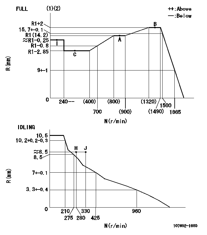
N:Pump speed
R:Rack position (mm)
(1)Torque cam stamping: T1
(2)Tolerance for racks not indicated: +-0.05mm.
----------
T1=AH10
----------
----------
T1=AH10
----------
Speed control lever angle
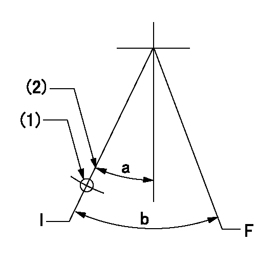
F:Full speed
I:Idle
(1)Use the pin at R = aa
(2)Stopper bolt setting
----------
aa=68mm
----------
a=17deg+-5deg b=36deg+-3deg
----------
aa=68mm
----------
a=17deg+-5deg b=36deg+-3deg
Stop lever angle
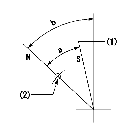
N:Pump normal
S:Stop the pump.
(1)Set the stopper bolt at speed = aa and rack position = bb (non-injection rack position).
(2)Use the pin above R = cc
----------
aa=0r/min bb=1.5+-0.3mm cc=40mm
----------
a=44deg+-5deg b=44deg+-5deg
----------
aa=0r/min bb=1.5+-0.3mm cc=40mm
----------
a=44deg+-5deg b=44deg+-5deg
0000001301

(1)Pump vertical direction
(2)Positions of coupling's threaded installation holes at No 1 cylinder's beginning of injection
(3)B.T.D.C.: aa
(4)Pre-stroke: bb
----------
aa=6deg bb=5.1+-0.03mm
----------
a=(140deg)
----------
aa=6deg bb=5.1+-0.03mm
----------
a=(140deg)
0000001401

(1)Pointer
(2)Injection timing aligning mark
(3)Fly weight
(4)The actual shape and direction may be different from this illustration.
Operation sequence
1. Turn the prestroke actuator OFF.
2. Turn the camshaft as far as the No.1 cylinder's beginning of injection position.
3. Check that the pointer alignment mark of the injection pump and the alignment mark of the flywheel are matching.
4. If they are not matching, erase the alignment mark on the flywheel side, and stamp an alignment mark on the flywheel position that matches with the pointer side alignment mark.
5. Check again that the coupling's key groove position is in the No.1 cylinder's beginning of injection position.
----------
----------
----------
----------
0000001701

A : Stopper pin
B: Connector
----------
----------
----------
----------
0000001801

C:Shim
----------
----------
----------
----------
0000001901

A:Sealing position
B:Pre-stroke actuator
1. When installing the pre-stroke actuator on the pump, first tighten the installation bolts loosely, then move the actuator fully clockwise (viewed from the drive side).
Temporary tightening torque: 1 - 1.5 N.m (0.1 - 0.15 kgf.m)
2. Move the actuator in the counterclockwise direction when viewed from the drive side, and adjust so that it becomes the adjustment point of the adjustment value. Then tighten it.
Tightening torque: 7^9 N.m (0.7^0.9 kgf.m)
3. After prestroke actuator installation adjustment, simultaneously stamp both the actuator side and housing side.
----------
----------
----------
----------
0000002201 RACK SENSOR
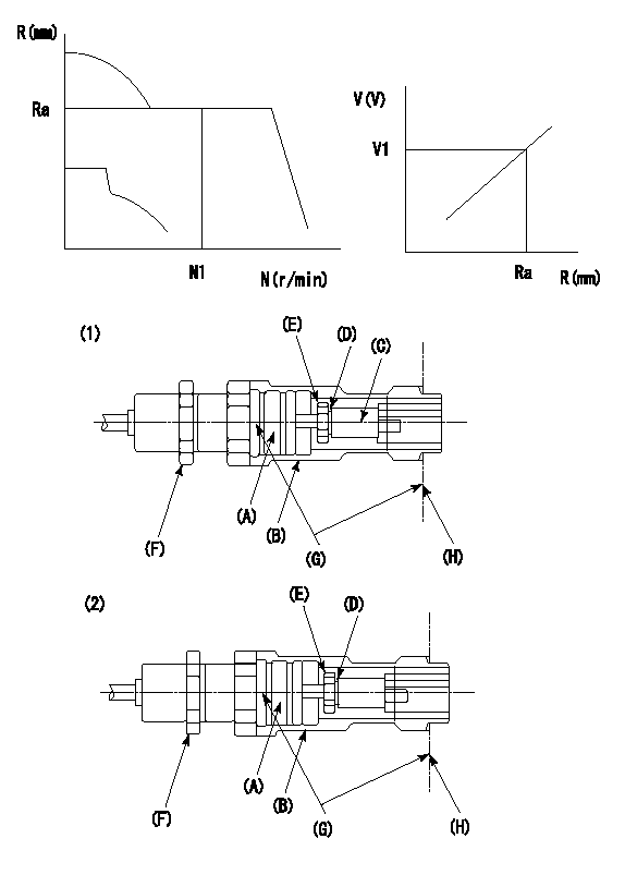
G:Red paint
H:Pump end face
P/N: part number of suitable shim
(1)Threaded type rack block
(2)Welded type rack block
Rack sensor adjustment
1. Threaded type rack sensor (-5*20, P type, no TICS rack limit).
(1)Screw in the bobbin (A) until it contacts the joint (B).
(2)Fix the pump lever.
(3)At speed N1 and rack position Ra, adjust the amount that the bobbin is screwed in so that the amp's output voltage is V1.
(4)Fix using the nut (F).
(5)Affix the caution plate to the upper part of the joint (B).
(6)Apply (G) at two places.
Connecting part between the joint (B) and the nut (F)
Connecting part between the end surface of the pump (H) and the joint (B)
2. Range for screw-in adjustment between the bobbin (A) and the joint (B) is 9 threads.
Screw in to the end from (the position where the bobbin (A) is rotated 9 turns).
Speed N1, rack position Ra, output voltage V1, rack sensor supply voltage 5+-0.01 (V)
----------
Ra=R1(14.2)+2mm N1=1450r/min V1=3+-0.01V
----------
----------
Ra=R1(14.2)+2mm N1=1450r/min V1=3+-0.01V
----------
Information:
Under the Hood Inspection
For maximum service life of your truck engine, make a thorough under the hood inspection before starting the engine. Look for such items as oil or coolant leaks, loose bolts, worn fan belts and trash build-up. Remove trash build-up and have repairs made as needed. * Inspect the radiator for leaks and trash build-up. * Inspect the radiator hoses for cracks and loose clamps.* Inspect the fan and accessory drive belts for cracks, breaks or other damage. Belts for multiple groove pulleys are sold in matched sets. Belts for multiple groove pulleys must be replaced as matched sets. If only one belt of a two or three belt set is replaced, it will carry more of a load than the belts not replaced since the older belts are stretched. The additional load on the new belt could cause it to break. * Inspect the water pump for leaks. The water pump seal is lubricated by coolant in the cooling system. It is normal for a small amount of leakage to occur as the engine cools down and parts contract. * Inspect the engine for oil leaks, such as front and rear crankshaft seals, crankcase, oil filter and valve covers.* Inspect the fuel system for leaks, loose fuel line clamps and fittings and loose or worn hoses. If leaking is observed, find the source and correct the leak. If leaking is suspected, check the fluid levels more frequently than the recommended service intervals prescribed in this publication until a leak is found or fixed, or until the suspicion for a leak has been proven to be unwarranted. * Inspect wiring for loose connections and worn or frayed wires.* Inspect air intake system hoses and elbows for cracks and loose clamps.* Inspect engine-to-frame ground strap for good connection and condition.Pre-Start Checks
* Measure the engine crankcase oil level. The correct oil level is shown by the marks between the words "ADD" and "FULL RANGE" on the dipstick (oil level gauge) on the "Engine Stopped" side.The location of the ADD and FULL RANGE marks on the engine dipstick are determined by the tilt angle of the engine after it is installed in the truck.If the ADD and FULL RANGE marks have not been stamped on the dipstick, see "Calibration" in the "Dipsticks" section of this manual or contact your authorized Caterpillar dealer. * Check the coolant level with the engine stopped and cold. Remove the filler cap slowly to relieve pressure.* Maintain the coolant level to within 1/2 inch (13 mm) of the bottom of the fill pipe. Install the filler cap.* If equipped with a sight glass, maintain the coolant to the proper level.
To prevent engine damage, never add coolant to an overheated engine. Allow the engine to cool first.
Typical Example* Observe the air cleaner service indicator (if equipped). Service the air cleaner when the yellow diaphragm enters the red zone or the red piston locks in the visible position. If your truck air cleaner is not equipped