Information injection-pump assembly
BOSCH
9 400 612 391
9400612391
ZEXEL
107692-1580
1076921580
ISUZU
8976014170
8976014170
Rating:
Service parts 107692-1580 INJECTION-PUMP ASSEMBLY:
1.
_
5.
AUTOM. ADVANCE MECHANIS
7.
COUPLING PLATE
11.
Nozzle and Holder
8-94392-233-2
12.
Open Pre:MPa(Kqf/cm2)
18.1{185}/22.1{225}
14.
NOZZLE
Include in #1:
107692-1580
as INJECTION-PUMP ASSEMBLY
Cross reference number
BOSCH
9 400 612 391
9400612391
ZEXEL
107692-1580
1076921580
ISUZU
8976014170
8976014170
Zexel num
Bosch num
Firm num
Name
Calibration Data:
Adjustment conditions
Test oil
1404 Test oil ISO4113 or {SAEJ967d}
1404 Test oil ISO4113 or {SAEJ967d}
Test oil temperature
degC
40
40
45
Nozzle and nozzle holder
105780-8250
Bosch type code
1 688 901 101
Nozzle
105780-0120
Bosch type code
1 688 901 990
Nozzle holder
105780-2190
Opening pressure
MPa
20.7
Opening pressure
kgf/cm2
211
Injection pipe
Outer diameter - inner diameter - length (mm) mm 8-3-600
Outer diameter - inner diameter - length (mm) mm 8-3-600
Overflow valve
131425-1820
Overflow valve opening pressure
kPa
255
221
289
Overflow valve opening pressure
kgf/cm2
2.6
2.25
2.95
Tester oil delivery pressure
kPa
255
255
255
Tester oil delivery pressure
kgf/cm2
2.6
2.6
2.6
PS/ACT control unit part no.
407980-2
24*
Digi switch no.
17
Direction of rotation (viewed from drive side)
Left L
Left L
Injection timing adjustment
Direction of rotation (viewed from drive side)
Left L
Left L
Injection order
1-5-3-6-
2-4
Pre-stroke
mm
5.1
5.07
5.13
Beginning of injection position
Governor side NO.1
Governor side NO.1
Difference between angles 1
Cal 1-5 deg. 60 59.75 60.25
Cal 1-5 deg. 60 59.75 60.25
Difference between angles 2
Cal 1-3 deg. 120 119.75 120.25
Cal 1-3 deg. 120 119.75 120.25
Difference between angles 3
Cal 1-6 deg. 180 179.75 180.25
Cal 1-6 deg. 180 179.75 180.25
Difference between angles 4
Cyl.1-2 deg. 240 239.75 240.25
Cyl.1-2 deg. 240 239.75 240.25
Difference between angles 5
Cal 1-4 deg. 300 299.75 300.25
Cal 1-4 deg. 300 299.75 300.25
Injection quantity adjustment
Adjusting point
-
Rack position
13.7
Pump speed
r/min
850
850
850
Average injection quantity
mm3/st.
121.5
119.9
123.1
Max. variation between cylinders
%
0
-2.5
2.5
Basic
*
Fixing the rack
*
PS407980-224*
V
2.25+-0.
01
PS407980-224*
mm
3.1+-0.0
5
Standard for adjustment of the maximum variation between cylinders
*
Injection quantity adjustment_02
Adjusting point
Z
Rack position
7.5+-0.5
Pump speed
r/min
435
435
435
Average injection quantity
mm3/st.
8.5
7.2
9.8
Max. variation between cylinders
%
0
-14
14
Fixing the rack
*
PS407980-224*
V
V1+0.05+
-0.01
PS407980-224*
mm
5+-0.03
Standard for adjustment of the maximum variation between cylinders
*
Remarks
Refer to items regarding the pre-stroke actuator
Refer to items regarding the pre-stroke actuator
Injection quantity adjustment_03
Adjusting point
A
Rack position
R1(13.7)
Pump speed
r/min
850
850
850
Average injection quantity
mm3/st.
121.5
120.5
122.5
Basic
*
Fixing the lever
*
PS407980-224*
V
2.25+-0.
01
PS407980-224*
mm
3.1+-0.0
5
Injection quantity adjustment_04
Adjusting point
B
Rack position
R1+2.2
Pump speed
r/min
1400
1400
1400
Average injection quantity
mm3/st.
123.5
113.5
133.5
Fixing the lever
*
PS407980-224*
V
2.25+-0.
01
PS407980-224*
mm
3.1+-0.0
5
0000001601
CU407980-224*
*
Actuator retarding type
*
Supply voltage
V
24
23.5
24.5
Ambient temperature
degC
23
18
28
Pre-stroke
mm
2
1.95
2.05
Output voltage
V
2.83
2.82
2.84
Adjustment
*
_02
CU407980-224*
*
Supply voltage
V
24
23.5
24.5
Ambient temperature
degC
23
18
28
Pre-stroke
mm
5.1
5.07
5.13
Output voltage
V
1.2
1
1.4
Confirmation
*
Remarks
Output voltage V1
Output voltage V1
_03
CU407980-224*
*
Supply voltage
V
24
23.5
24.5
Ambient temperature
degC
23
18
28
Output voltage
V
3.05
3.05
Confirmation of operating range
*
Test data Ex:
Governor adjustment
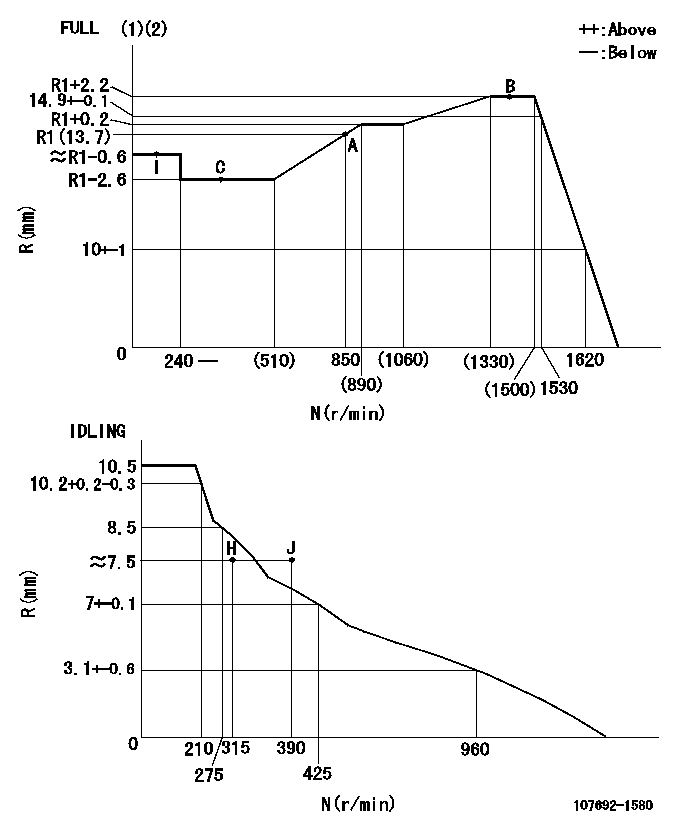
N:Pump speed
R:Rack position (mm)
(1)Torque cam stamping: T1
(2)Tolerance for racks not indicated: +-0.05mm.
----------
T1=AF89
----------
----------
T1=AF89
----------
Speed control lever angle
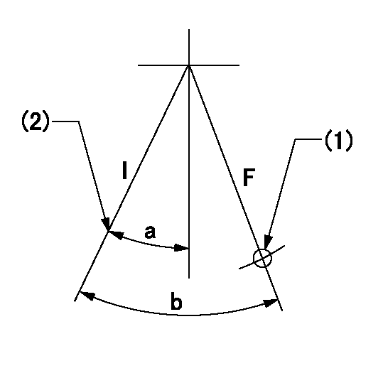
F:Full speed
I:Idle
(1)Use the pin at R = aa
(2)Stopper bolt set position 'H'
----------
aa=68mm
----------
a=19.5deg+-5deg b=43.5deg+-3deg
----------
aa=68mm
----------
a=19.5deg+-5deg b=43.5deg+-3deg
Stop lever angle
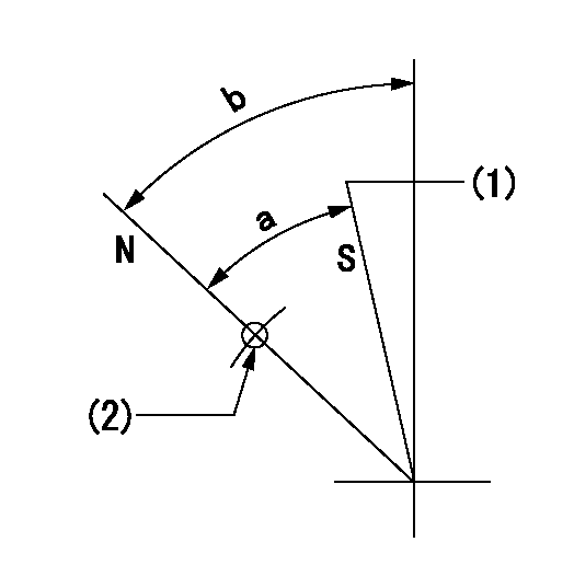
N:Pump normal
S:Stop the pump.
(1)Set the stopper bolt at speed = aa and rack position = bb.
(2)Use the pin above R = cc
----------
aa=0r/min bb=1.5+-0.3mm cc=40mm
----------
a=44deg+-5deg b=44deg+-5deg
----------
aa=0r/min bb=1.5+-0.3mm cc=40mm
----------
a=44deg+-5deg b=44deg+-5deg
0000001301

(1)Pump vertical direction
(2)Positions of coupling's threaded installation holes at No 1 cylinder's beginning of injection
(3)B.T.D.C.: aa
(4)Pre-stroke: bb
----------
aa=8deg bb=5.1+-0.03mm
----------
a=(140deg)
----------
aa=8deg bb=5.1+-0.03mm
----------
a=(140deg)
0000001401

(1)Pointer
(2)Injection timing aligning mark
(3)Fly weight
(4)The actual shape and direction may be different from this illustration.
Operation sequence
1. Turn the prestroke actuator OFF.
2. Turn the camshaft as far as the No.1 cylinder's beginning of injection position.
3. Check that the pointer alignment mark of the injection pump and the alignment mark of the flywheel are matching.
4. If they are not matching, erase the alignment mark on the flywheel side, and stamp an alignment mark on the flywheel position that matches with the pointer side alignment mark.
5. Check again that the coupling's key groove position is in the No.1 cylinder's beginning of injection position.
----------
----------
----------
----------
0000001701

A : Stopper pin
B: Connector
----------
----------
----------
----------
0000001801

C:Shim
----------
----------
----------
----------
0000001901

A:Sealing position
B:Pre-stroke actuator
1. When installing the pre-stroke actuator on the pump, first tighten the installation bolts loosely, then move the actuator fully clockwise (viewed from the drive side).
Temporary tightening torque: 1 - 1.5 N.m (0.1 - 0.15 kgf.m)
2. Move the actuator in the counterclockwise direction when viewed from the drive side, and adjust so that it becomes the adjustment point of the adjustment value. Then tighten it.
Tightening torque: 7^9 N.m (0.7^0.9 kgf.m)
3. After prestroke actuator installation adjustment, simultaneously stamp both the actuator side and housing side.
----------
----------
----------
----------
0000002201 AIR CYLINDER
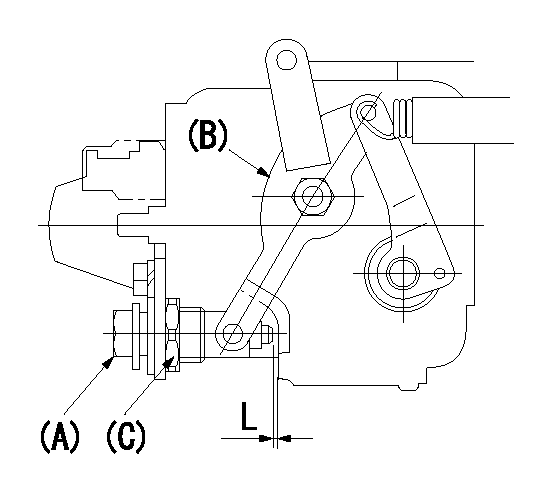
(a) Air cylinder
(b) Speed lever
(c) Lock nut
1. Air cylinder adjustment procedure
(1)Set the speed lever B in the idle position.
(2)Turn the air cylinder A ON.
(3)Screw in the air cylinder (a)
(4)Set the speed lever B so that the speed is N1 and the rack position is Ra.
(5)After setting, turn the air cylinder A off.
(6)Confirm that the distance between the speed lever B and the air cylinder A is approximately L.
----------
N1=365r/min Ra=7.5+-0.1mm L1=1mm
----------
----------
N1=365r/min Ra=7.5+-0.1mm L1=1mm
----------
0000002301 RACK SENSOR
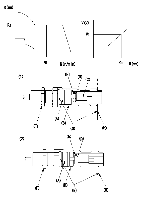
G:Red paint
H:Pump end face
P/N: part number of suitable shim
(1)Threaded type rack block
(2)Welded type rack block
Rack sensor adjustment
1. Threaded type rack sensor (-5*20, P type, no TICS rack limit).
(1)Screw in the bobbin (A) until it contacts the joint (B).
(2)Fix the pump lever.
(3)At speed N1 and rack position Ra, adjust the amount that the bobbin is screwed in so that the amp's output voltage is V1.
(4)Fix using the nut (F).
(5)Affix the caution plate to the upper part of the joint (B).
(6)Apply (G) at two places.
Connecting part between the joint (B) and the nut (F)
Connecting part between the end surface of the pump (H) and the joint (B)
2. Range for screw-in adjustment between the bobbin (A) and the joint (B) is 9 threads.
Screw in to the end from (the position where the bobbin (A) is rotated 9 turns).
Speed N1, rack position Ra, output voltage V1, rack sensor supply voltage 5+-0.01 (V)
----------
Ra=R1(13.7)+2.2mm N1=1400r/min V1=3+-0.01V
----------
----------
Ra=R1(13.7)+2.2mm N1=1400r/min V1=3+-0.01V
----------
Information:
Caterpillar Diesel Truck Engines can operate effectively in cold weather, however, engine operation in cold weather is dependent on the type of fuel used and how well the fuel moves through fuel related components. The purpose of this section is to explain some of the problems and steps that can be taken to minimize fuel problems during cold weather operation when the engine area is colder than 5°C (40°F).Fuel And The Effect From Cold Weather
The two types of diesel fuel available for your engine are typically grades No. 1 and No. 2. Although No. 2 diesel fuel is the most commonly used fuel, No. 1 diesel fuel is the fuel that is best suited for cold weather operation.During cold weather operation, it may be necessary for you to use No. 2 diesel fuel since quantities of No. 1 diesel fuel are limited and generally are only available during the winter months and in the colder climates.There are two major differences between No. 1 and No. 2 diesel fuel. No. 1 diesel fuel has a lower cloud point and a lower pour point.The cloud point is the temperature at which a cloud or haze of wax crystals will begin to form in the fuel and cause fuel filters to plug. The pour point is the temperature which diesel fuel will begin to thicken and be more resistant to flow through fuel pumps and lines.Be aware of these fuel values when purchasing your diesel fuel and anticipate the average outside (ambient) temperature for the area your engine will be operating. Engines fueled in one climate may not operate satisfactorily if moved to another because of problems that result from cold weather. The average No. 1 diesel fuel has a lower kJ (BTU) (heat content) rating per unit volume of fuel than the average No. 2 diesel fuel. When using No. 1 diesel fuel, you may notice a drop in power and fuel efficiency, but should not experience any other operating effects.Before troubleshooting for low power or poor performance in winter months, check the type of fuel being used.The use of starting aids, engine oil pan heaters, engine coolant heaters, fuel heaters and fuel line insulation also provide a means of minimizing starting and fuel problems in cold weather when No. 2 diesel fuel is used.Fuel Related Components In Cold Weather
Fuel Heaters
Fuel heaters prevent plugging of the fuel filters in cold weather due to waxing. Non-thermostatically controlled fuel heaters can heat the fuel in excess of 65°C (150°F). High fuel temperatures reduce engine performance and reliability.A fuel heater should be installed so that the fuel is heated before it enters the first (primary) fuel filter.Use a fuel heater that is mechanically simple, yet adequate for the application. The fuel heater should also prevent overheating of the fuel. Choose a fuel heater with as large a heating surface as practical. Small heaters can be too hot in their limited surface area.Disconnect or deactivate the fuel heater in warm weather. A loss of