Information injection-pump assembly
BOSCH
9 400 619 019
9400619019
ZEXEL
107692-1483
1076921483
ISUZU
8976005772
8976005772

Rating:
Service parts 107692-1483 INJECTION-PUMP ASSEMBLY:
1.
_
5.
AUTOM. ADVANCE MECHANIS
7.
COUPLING PLATE
11.
Nozzle and Holder
12.
Open Pre:MPa(Kqf/cm2)
18.1(185)/22.1(225)
14.
NOZZLE
Include in #1:
107692-1483
as INJECTION-PUMP ASSEMBLY
Cross reference number
BOSCH
9 400 619 019
9400619019
ZEXEL
107692-1483
1076921483
ISUZU
8976005772
8976005772
Zexel num
Bosch num
Firm num
Name
107692-1483
9 400 619 019
8976005772 ISUZU
INJECTION-PUMP ASSEMBLY
6HH1 * K
6HH1 * K
Calibration Data:
Adjustment conditions
Test oil
1404 Test oil ISO4113 or {SAEJ967d}
1404 Test oil ISO4113 or {SAEJ967d}
Test oil temperature
degC
40
40
45
Nozzle and nozzle holder
105780-8250
Bosch type code
1 688 901 101
Nozzle
105780-0120
Bosch type code
1 688 901 990
Nozzle holder
105780-2190
Opening pressure
MPa
20.7
Opening pressure
kgf/cm2
211
Injection pipe
Outer diameter - inner diameter - length (mm) mm 8-3-600
Outer diameter - inner diameter - length (mm) mm 8-3-600
Overflow valve
131425-1820
Overflow valve opening pressure
kPa
255
255
255
Overflow valve opening pressure
kgf/cm2
2.6
2.6
2.6
Tester oil delivery pressure
kPa
255
255
255
Tester oil delivery pressure
kgf/cm2
2.6
2.6
2.6
PS/ACT control unit part no.
407980-2
24*
Digi switch no.
17
Direction of rotation (viewed from drive side)
Left L
Left L
Injection timing adjustment
Direction of rotation (viewed from drive side)
Left L
Left L
Injection order
1-5-3-6-
2-4
Pre-stroke
mm
5.1
5.07
5.13
Beginning of injection position
Governor side NO.1
Governor side NO.1
Difference between angles 1
Cal 1-5 deg. 60 59.75 60.25
Cal 1-5 deg. 60 59.75 60.25
Difference between angles 2
Cal 1-3 deg. 120 119.75 120.25
Cal 1-3 deg. 120 119.75 120.25
Difference between angles 3
Cal 1-6 deg. 180 179.75 180.25
Cal 1-6 deg. 180 179.75 180.25
Difference between angles 4
Cyl.1-2 deg. 240 239.75 240.25
Cyl.1-2 deg. 240 239.75 240.25
Difference between angles 5
Cal 1-4 deg. 300 299.75 300.25
Cal 1-4 deg. 300 299.75 300.25
Injection quantity adjustment
Adjusting point
-
Rack position
13.8
Pump speed
r/min
850
850
850
Average injection quantity
mm3/st.
116
114.4
117.6
Max. variation between cylinders
%
0
-2.5
2.5
Basic
*
Fixing the rack
*
PS407980-224*
V
2.25+-0.
01
PS407980-224*
mm
3.1+-0.0
5
Standard for adjustment of the maximum variation between cylinders
*
Injection quantity adjustment_02
Adjusting point
Z
Rack position
8.5+-0.5
Pump speed
r/min
360
360
360
Average injection quantity
mm3/st.
12
10.7
13.3
Max. variation between cylinders
%
0
-14
14
Fixing the rack
*
PS407980-224*
V
V1+0.05+
-0.01
PS407980-224*
mm
5+-0.03
Standard for adjustment of the maximum variation between cylinders
*
Remarks
Refer to items regarding the pre-stroke actuator
Refer to items regarding the pre-stroke actuator
Injection quantity adjustment_03
Adjusting point
A
Rack position
R1(13.8)
Pump speed
r/min
850
850
850
Average injection quantity
mm3/st.
116
115
117
Basic
*
Fixing the lever
*
PS407980-224*
V
2.25+-0.
01
PS407980-224*
mm
3.1+-0.0
5
Injection quantity adjustment_04
Adjusting point
B
Rack position
[R1+2.4]
+-0.02
Pump speed
r/min
1450
1450
1450
Average injection quantity
mm3/st.
121
111
131
Fixing the lever
*
PS407980-224*
V
2.25+-0.
01
PS407980-224*
mm
3.1+-0.0
5
0000001601
CU407980-224*
*
Actuator retarding type
*
Supply voltage
V
24
23.5
24.5
Ambient temperature
degC
23
18
28
Pre-stroke
mm
2
1.95
2.05
Output voltage
V
2.83
2.82
2.84
Adjustment
*
_02
CU407980-224*
*
Supply voltage
V
24
23.5
24.5
Ambient temperature
degC
23
18
28
Pre-stroke
mm
5.1
5.07
5.13
Output voltage
V
1.2
1
1.4
Confirmation
*
Remarks
Output voltage V1
Output voltage V1
_03
CU407980-224*
*
Supply voltage
V
24
23.5
24.5
Ambient temperature
degC
23
18
28
Output voltage
V
3.05
3.05
Confirmation of operating range
*
Test data Ex:
Governor adjustment
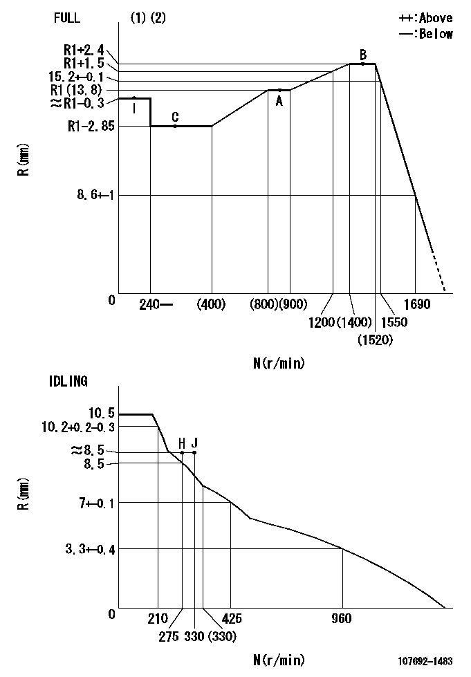
N:Pump speed
R:Rack position (mm)
(1)Torque cam stamping: T1
(2)Tolerance for racks not indicated: +-0.05mm.
----------
T1=AF71
----------
----------
T1=AF71
----------
Speed control lever angle

F:Full speed
I:Idle
(1)Use the pin at R = aa
(2)Stopper bolt setting
----------
aa=35mm
----------
a=1deg+-5deg b=39.5deg+-3deg
----------
aa=35mm
----------
a=1deg+-5deg b=39.5deg+-3deg
Stop lever angle
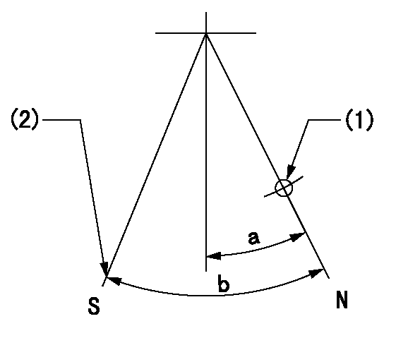
N:Pump normal
S:Stop the pump.
(1)Use the pin at R = aa
(2)At pump speed bb and rack position cc, set the stopper bolt.
----------
aa=40mm bb=0r/min cc=1.5+-0.3mm
----------
a=12deg+-5deg b=44deg+-5deg
----------
aa=40mm bb=0r/min cc=1.5+-0.3mm
----------
a=12deg+-5deg b=44deg+-5deg
0000001301

(1)Pump vertical direction
(2)Positions of coupling's threaded installation holes at No 1 cylinder's beginning of injection
(3)B.T.D.C.: aa
(4)Pre-stroke: bb
----------
aa=6deg bb=5.1+-0.03mm
----------
a=(140deg)
----------
aa=6deg bb=5.1+-0.03mm
----------
a=(140deg)
0000001401

(1)Pointer
(2)Injection timing aligning mark
(3)Fly weight
(4)The actual shape and direction may be different from this illustration.
Operation sequence
1. Turn the prestroke actuator OFF.
2. Turn the camshaft as far as the No.1 cylinder's beginning of injection position.
3. Check that the pointer alignment mark of the injection pump and the alignment mark of the flywheel are matching.
4. If they are not matching, erase the alignment mark on the flywheel side, and stamp an alignment mark on the flywheel position that matches with the pointer side alignment mark.
5. Check again that the coupling's key groove position is in the No.1 cylinder's beginning of injection position.
----------
----------
----------
----------
0000001701

A : Stopper pin
B: Connector
----------
----------
----------
----------
0000001801

C:Shim
----------
----------
----------
----------
0000001901

A:Sealing position
B:Pre-stroke actuator
1. When installing the pre-stroke actuator on the pump, first tighten the installation bolts loosely, then move the actuator fully clockwise (viewed from the drive side).
Temporary tightening torque: 1 - 1.5 N.m (0.1 - 0.15 kgf.m)
2. Move the actuator in the counterclockwise direction when viewed from the drive side, and adjust so that it becomes the adjustment point of the adjustment value. Then tighten it.
Tightening torque: 7^9 N.m (0.7^0.9 kgf.m)
3. After prestroke actuator installation adjustment, simultaneously stamp both the actuator side and housing side.
----------
----------
----------
----------
0000002201 RACK SENSOR
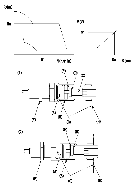
G:Red paint
H:Pump end face
P/N: part number of suitable shim
(1)Threaded type rack block
(2)Welded type rack block
Rack sensor adjustment
1. Threaded type rack sensor (-5*20, P type, no TICS rack limit).
(1)Screw in the bobbin (A) until it contacts the joint (B).
(2)Fix the pump lever.
(3)At speed N1 and rack position Ra, adjust the amount that the bobbin is screwed in so that the amp's output voltage is V1.
(4)Fix using the nut (F).
(5)Affix the caution plate to the upper part of the joint (B).
(6)Apply (G) at two places.
Connecting part between the joint (B) and the nut (F)
Connecting part between the end surface of the pump (H) and the joint (B)
2. Range for screw-in adjustment between the bobbin (A) and the joint (B) is 9 threads.
Screw in to the end from (the position where the bobbin (A) is rotated 9 turns).
Speed N1, rack position Ra, output voltage V1, rack sensor supply voltage 5+-0.01 (V)
----------
Ra=R1(13.8)+2.4mm N1=1450r/min V1=3+-0.01V
----------
----------
Ra=R1(13.8)+2.4mm N1=1450r/min V1=3+-0.01V
----------
Information:
Your engine may not have the same or all of the gauges as shown in the illustrations. The illustrations shown are of typical gauges.Gauges provide a "look" inside the engine. Be sure they are in good working order. You can determine what is the "normal" operating range by observing your gauges over a period of time.Noticeable changes in gauge readings are an indication of potential gauge or engine problems. This also applies to gauge readings that have changed significantly but are still within specifications. The cause of any sudden or significant change in the readings should be determined and corrected. Contact your Caterpillar dealer for assistance as needed. Oil Pressure - Indicates engine oil pressure. Normal oil pressure should read 275 to 606 kPa (40 to 88 psi) when the engine is running at rated engine rpm, with SAE 10W30 oil, at 110°C (230°F) operating oil temperature.If the gauge reading fluctuates after the load is stable:1. Remove the load.2. Reduce engine speed to low idle.The DIAGNOSTIC lamp will come on and a fault logged in the ECM system if oil pressure drops below 69 kPa (10 psi) at low idle rpm. If no pressure is indicated, stop the engine. Jacket Water Temperature - Indicates engine coolant temperature. The gauge should normally indicate between 87 and 98°C (189 and 208°F). Somewhat higher temperatures may occur under certain conditions. Maximum allowable operating temperature is 104°C (220°F) with the cooling system pressurized. If the engine is operating above this range and steam becomes apparent:1. Reduce the load and engine rpm.2. Inspect for coolant leaks.3. Determine if the engine must be shutdown immediately; or if the engine can be cooled by reducing the load.A DIAGNOSTIC lamp will come on and a fault logged in the ECM if jacket water temperature is above 104°C (220°F). Fuel Pressure - Indicates fuel pressure to the injection pump. The indicator should register in the NORMAL (green) range. Normal fuel pressure at LOW IDLE is 205 35 kPa (30 5 psi). Normal fuel pressure at Top Engine Limit (TEL) or rated rpm is 240 kPa (35 psi).If the indicator moves to the OUT position or registers below 160 kPa (23 psi) when equipped with a numerical gauge, the engine will not operate properly. A drop in fuel pressure usually indicates a dirty or plugged fuel filter. Tachometer - Indicates engine rpm. The engine can be operated at top engine limit (2300 rpm max) without damage, but should never be allowed to exceed 2450 rpm. Overspeeding can result in serious damage to your engine.
To prevent engine damage, never exceed 2450 rpm.
Service Hour Meter - Indicates the total number of clock hours the engine has operated if used. ECM Hours are also available via ECAP.
To prevent engine damage, never exceed 2450 rpm.
Service Hour Meter - Indicates the total number of clock hours the engine has operated if used. ECM Hours are also available via ECAP.
Have questions with 107692-1483?
Group cross 107692-1483 ZEXEL
Isuzu
Isuzu
Isuzu
Isuzu
Isuzu
Isuzu
Isuzu
Isuzu
107692-1483
9 400 619 019
8976005772
INJECTION-PUMP ASSEMBLY
6HH1
6HH1