Information injection-pump assembly
BOSCH
9 400 619 010
9400619010
ZEXEL
107692-1344
1076921344
ISUZU
8943907965
8943907965
Rating:
Cross reference number
BOSCH
9 400 619 010
9400619010
ZEXEL
107692-1344
1076921344
ISUZU
8943907965
8943907965
Zexel num
Bosch num
Firm num
Name
107692-1344
9 400 619 010
8943907965 ISUZU
INJECTION-PUMP ASSEMBLY
6HH1 K
6HH1 K
Calibration Data:
Adjustment conditions
Test oil
1404 Test oil ISO4113 or {SAEJ967d}
1404 Test oil ISO4113 or {SAEJ967d}
Test oil temperature
degC
40
40
45
Nozzle and nozzle holder
105780-8250
Bosch type code
1 688 901 101
Nozzle
105780-0120
Bosch type code
1 688 901 990
Nozzle holder
105780-2190
Opening pressure
MPa
20.7
Opening pressure
kgf/cm2
211
Injection pipe
Outer diameter - inner diameter - length (mm) mm 8-3-600
Outer diameter - inner diameter - length (mm) mm 8-3-600
Overflow valve
131425-1820
Overflow valve opening pressure
kPa
255
221
289
Overflow valve opening pressure
kgf/cm2
2.6
2.25
2.95
Tester oil delivery pressure
kPa
255
255
255
Tester oil delivery pressure
kgf/cm2
2.6
2.6
2.6
PS/ACT control unit part no.
407980-2
24*
Digi switch no.
17
Direction of rotation (viewed from drive side)
Left L
Left L
Injection timing adjustment
Direction of rotation (viewed from drive side)
Left L
Left L
Injection order
1-5-3-6-
2-4
Pre-stroke
mm
5.1
5.07
5.13
Beginning of injection position
Governor side NO.1
Governor side NO.1
Difference between angles 1
Cal 1-5 deg. 60 59.75 60.25
Cal 1-5 deg. 60 59.75 60.25
Difference between angles 2
Cal 1-3 deg. 120 119.75 120.25
Cal 1-3 deg. 120 119.75 120.25
Difference between angles 3
Cal 1-6 deg. 180 179.75 180.25
Cal 1-6 deg. 180 179.75 180.25
Difference between angles 4
Cyl.1-2 deg. 240 239.75 240.25
Cyl.1-2 deg. 240 239.75 240.25
Difference between angles 5
Cal 1-4 deg. 300 299.75 300.25
Cal 1-4 deg. 300 299.75 300.25
Injection quantity adjustment
Adjusting point
-
Rack position
13.8
Pump speed
r/min
850
850
850
Average injection quantity
mm3/st.
116
114.4
117.6
Max. variation between cylinders
%
0
-2.5
2.5
Basic
*
Fixing the rack
*
PS407980-224*
V
2.25+-0.
01
PS407980-224*
mm
3.1+-0.0
5
Standard for adjustment of the maximum variation between cylinders
*
Injection quantity adjustment_02
Adjusting point
Z
Rack position
8.5+-0.5
Pump speed
r/min
360
360
360
Average injection quantity
mm3/st.
12
10.7
13.3
Max. variation between cylinders
%
0
-14
14
Fixing the rack
*
PS407980-224*
V
V1+0.05+
-0.01
PS407980-224*
mm
5+-0.03
Standard for adjustment of the maximum variation between cylinders
*
Remarks
Refer to items regarding the pre-stroke actuator
Refer to items regarding the pre-stroke actuator
Injection quantity adjustment_03
Adjusting point
A
Rack position
R1(13.8)
Pump speed
r/min
850
850
850
Average injection quantity
mm3/st.
116
115
117
Basic
*
Fixing the lever
*
PS407980-224*
V
2.25+-0.
01
PS407980-224*
mm
3.1+-0.0
5
Injection quantity adjustment_04
Adjusting point
B
Rack position
(R1+2.4)
+-0.02
Pump speed
r/min
1450
1450
1450
Average injection quantity
mm3/st.
121
111
131
Fixing the lever
*
PS407980-224*
V
2.25+-0.
01
PS407980-224*
mm
3.1+-0.0
5
0000001601
CU407980-224*
*
Actuator retarding type
*
Supply voltage
V
24
23.5
24.5
Ambient temperature
degC
23
18
28
Pre-stroke
mm
2
1.95
2.05
Output voltage
V
2.83
2.82
2.84
Adjustment
*
_02
CU407980-224*
*
Supply voltage
V
24
23.5
24.5
Ambient temperature
degC
23
18
28
Pre-stroke
mm
5.1
5.07
5.13
Output voltage
V
1.2
1
1.4
Confirmation
*
Remarks
Output voltage V1
Output voltage V1
_03
CU407980-224*
*
Supply voltage
V
24
23.5
24.5
Ambient temperature
degC
23
18
28
Output voltage
V
3.05
3.05
Confirmation of operating range
*
Test data Ex:
Governor adjustment
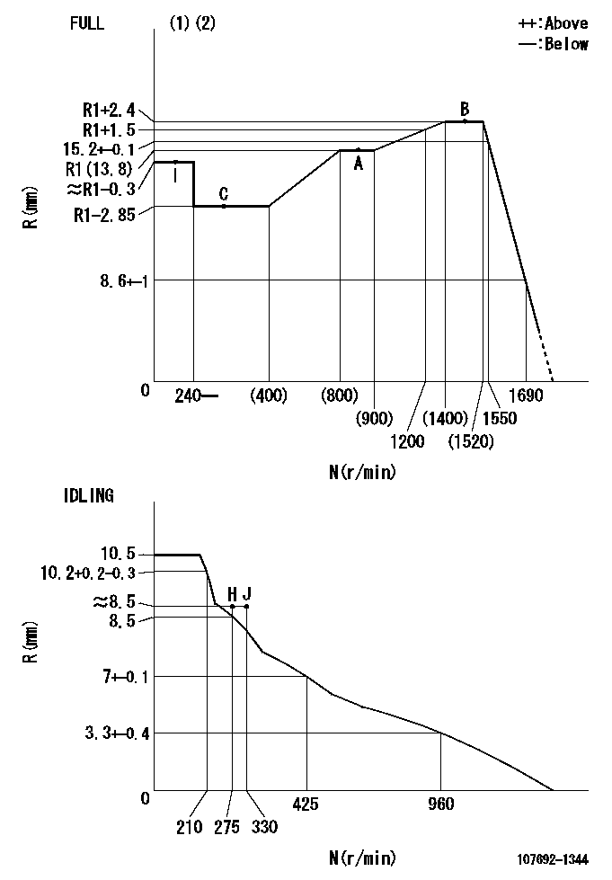
N:Pump speed
R:Rack position (mm)
(1)Torque cam stamping: T1
(2)Tolerance for racks not indicated: +-0.05mm.
----------
T1=AF71
----------
----------
T1=AF71
----------
Speed control lever angle

F:Full speed
I:Idle
(1)Use the pin at R = aa
(2)Stopper bolt set position 'H'
----------
aa=35mm
----------
a=1deg+-5deg b=39.5deg+-3deg
----------
aa=35mm
----------
a=1deg+-5deg b=39.5deg+-3deg
Stop lever angle
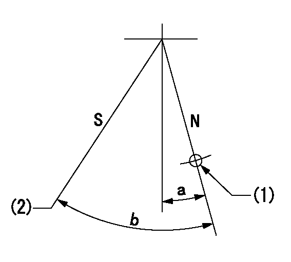
N:Pump normal
S:Stop the pump.
(1)Use the pin at R = aa
(2)Set the stopper bolt at rack position = bb, speed = cc
----------
aa=40mm bb=0r/min cc=1.5+-0.3mm
----------
a=12deg+-5deg b=44deg+-5deg
----------
aa=40mm bb=0r/min cc=1.5+-0.3mm
----------
a=12deg+-5deg b=44deg+-5deg
0000001301

(1)Pump vertical direction
(2)Positions of coupling's threaded installation holes at No 1 cylinder's beginning of injection
(3)B.T.D.C.: aa
(4)Pre-stroke: bb
----------
aa=6deg bb=5.1+-0.03mm
----------
a=(140deg)
----------
aa=6deg bb=5.1+-0.03mm
----------
a=(140deg)
0000001401

(1)Pointer
(2)Injection timing aligning mark
(3)Fly weight
(4)The actual shape and direction may be different from this illustration.
Operation sequence
1. Turn the prestroke actuator OFF.
2. Turn the camshaft as far as the No.1 cylinder's beginning of injection position.
3. Check that the pointer alignment mark of the injection pump and the alignment mark of the flywheel are matching.
4. If they are not matching, erase the alignment mark on the flywheel side, and stamp an alignment mark on the flywheel position that matches with the pointer side alignment mark.
5. Check again that the coupling's key groove position is in the No.1 cylinder's beginning of injection position.
----------
----------
----------
----------
0000001701

A : Stopper pin
B: Connector
----------
----------
----------
----------
0000001801

C:Shim
----------
----------
----------
----------
0000001901

A:Sealing position
B:Pre-stroke actuator
1. When installing the pre-stroke actuator on the pump, first tighten the installation bolts loosely, then move the actuator fully clockwise (viewed from the drive side).
Temporary tightening torque: 1 - 1.5 N.m (0.1 - 0.15 kgf.m)
2. Move the actuator in the counterclockwise direction when viewed from the drive side, and adjust so that it becomes the adjustment point of the adjustment value. Then tighten it.
Tightening torque: 7^9 N.m (0.7^0.9 kgf.m)
3. After prestroke actuator installation adjustment, simultaneously stamp both the actuator side and housing side.
----------
----------
----------
----------
0000002201 RACK SENSOR
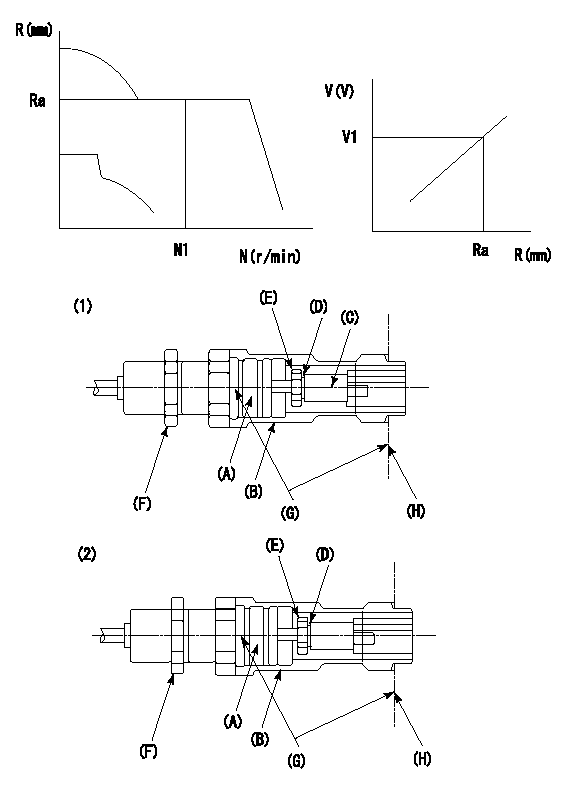
G:Red paint
H:Pump end face
P/N: part number of suitable shim
(1)Threaded type rack block
(2)Welded type rack block
Rack sensor adjustment
1. Threaded type rack sensor (-5*20, P type, no TICS rack limit).
(1)Screw in the bobbin (A) until it contacts the joint (B).
(2)Fix the pump lever.
(3)At speed N1 and rack position Ra, adjust the amount that the bobbin is screwed in so that the amp's output voltage is V1.
(4)Fix using the nut (F).
(5)Affix the caution plate to the upper part of the joint (B).
(6)Apply (G) at two places.
Connecting part between the joint (B) and the nut (F)
Connecting part between the end surface of the pump (H) and the joint (B)
2. Range for screw-in adjustment between the bobbin (A) and the joint (B) is 9 threads.
Screw in to the end from (the position where the bobbin (A) is rotated 9 turns).
Speed N1, rack position Ra, output voltage V1, rack sensor supply voltage 5+-0.01 (V)
----------
Ra=R1(13.8)+2.4mm N1=1450r/min V1=3+-0.01V
----------
----------
Ra=R1(13.8)+2.4mm N1=1450r/min V1=3+-0.01V
----------
Information:
Caterpillar Reference Material
The following literature can be obtained through any Caterpillar dealer. The literature specific for your engine can be found in the Information Section, Product Support topic in this manual.Oil
Oil and Your Engine SEBD0640Question & Answer Booklet PEDP7122Cat Lithium Grease (MPGL) PEHP0003Cat Special Purpose Grease (SPG) PEHP0017How to Take a Good Oil Sample PEHP6001Cat Engine Oil Spec Sheets PEHP7504Cat Diesel Engine Oil Spec Sheets PEHP7505Cat Fluids Selector PEWP9733Fuel
Diesel Fuels and Your Engine SEBD0717Coolant
Know Your Cooling System SEBD0518Coolant and Your Engine SEBD0970Miscellaneous
3406B Industrial and Marine Service Manual SENR3023Index to Guidelines for Reusable Parts and Salvage Operations SEBF8029Storage Procedure for Caterpillar Products SEHS9031The Caterpillar Engine Technical Manual (Volume I) LEO0002The Caterpillar Engine Technical Manual (Volume II) LEO0003All of the above publications are available through your Caterpillar dealer.Additional Reference Material
ASTM Specs can normally be obtained from your local technological society, library or college or contacting:* American Society for Testing and Materials
1916 Race St.
Philadelphia, PA 19103
(215) 299-5400
Society of Automotive Engineers (SAE) Specs can be found in your SAE handbook or can be obtained from your local library, college or technological society, or contacting:* Society of Automotive Engineers, Inc.
SAE International
400 Commonwealth Drive
Warrendale, PA USA 15096-0001
(412) 776-4841
American Petroleum Institute (API) classification system and oil selection for API Publication No. 1509 can be obtained from your local library, college or technological society, or contact:* American Petroleum Institute
1220 L St.
Washington, DC 20005
(202) 682-8000
Engine Manufacturers Association (EMA) information for lube oil selection can be obtained from your local library, college or technological society, or contact:* Engine Manufacturers Association
Lubricating Oils Data Book
401 N. Michigan Ave. Ste. 2400
Chicago, IL 60611
(312) 644-6610 ext. 3626
Have questions with 107692-1344?
Group cross 107692-1344 ZEXEL
Isuzu
Isuzu
107692-1344
9 400 619 010
8943907965
INJECTION-PUMP ASSEMBLY
6HH1
6HH1