Information injection-pump assembly
ZEXEL
107692-1280
1076921280
ISUZU
8943908910
8943908910
Rating:
Cross reference number
ZEXEL
107692-1280
1076921280
ISUZU
8943908910
8943908910
Zexel num
Bosch num
Firm num
Name
Calibration Data:
Adjustment conditions
Test oil
1404 Test oil ISO4113 or {SAEJ967d}
1404 Test oil ISO4113 or {SAEJ967d}
Test oil temperature
degC
40
40
45
Nozzle and nozzle holder
105780-8250
Bosch type code
1 688 901 101
Nozzle
105780-0120
Bosch type code
1 688 901 990
Nozzle holder
105780-2190
Opening pressure
MPa
20.7
Opening pressure
kgf/cm2
211
Injection pipe
Outer diameter - inner diameter - length (mm) mm 8-3-600
Outer diameter - inner diameter - length (mm) mm 8-3-600
Overflow valve
131425-1820
Overflow valve opening pressure
kPa
255
221
289
Overflow valve opening pressure
kgf/cm2
2.6
2.25
2.95
Tester oil delivery pressure
kPa
255
255
255
Tester oil delivery pressure
kgf/cm2
2.6
2.6
2.6
PS/ACT control unit part no.
407980-2
24*
Digi switch no.
17
Direction of rotation (viewed from drive side)
Left L
Left L
Injection timing adjustment
Direction of rotation (viewed from drive side)
Left L
Left L
Injection order
1-5-3-6-
2-4
Pre-stroke
mm
5.1
5.07
5.13
Beginning of injection position
Governor side NO.1
Governor side NO.1
Difference between angles 1
Cal 1-5 deg. 60 59.75 60.25
Cal 1-5 deg. 60 59.75 60.25
Difference between angles 2
Cal 1-3 deg. 120 119.75 120.25
Cal 1-3 deg. 120 119.75 120.25
Difference between angles 3
Cal 1-6 deg. 180 179.75 180.25
Cal 1-6 deg. 180 179.75 180.25
Difference between angles 4
Cyl.1-2 deg. 240 239.75 240.25
Cyl.1-2 deg. 240 239.75 240.25
Difference between angles 5
Cal 1-4 deg. 300 299.75 300.25
Cal 1-4 deg. 300 299.75 300.25
Injection quantity adjustment
Adjusting point
-
Rack position
14.2
Pump speed
r/min
850
850
850
Average injection quantity
mm3/st.
111
109.4
112.6
Max. variation between cylinders
%
0
-2.5
2.5
Basic
*
Fixing the rack
*
PS407980-224*
V
2.25+-0.
01
PS407980-224*
mm
3.1+-0.0
5
Standard for adjustment of the maximum variation between cylinders
*
Injection quantity adjustment_02
Adjusting point
Z
Rack position
9+-0.5
Pump speed
r/min
475
475
475
Average injection quantity
mm3/st.
12.5
11.2
13.8
Max. variation between cylinders
%
0
-14
14
Fixing the rack
*
PS407980-224*
V
V1+0.05+
-0.01
PS407980-224*
mm
5+-0.03
Standard for adjustment of the maximum variation between cylinders
*
Remarks
Refer to items regarding the pre-stroke actuator
Refer to items regarding the pre-stroke actuator
Injection quantity adjustment_03
Adjusting point
A
Rack position
R1(14.2)
Pump speed
r/min
850
850
850
Average injection quantity
mm3/st.
111
110
112
Basic
*
Fixing the lever
*
PS407980-224*
V
2.25+-0.
01
PS407980-224*
mm
3.1+-0.0
5
0000001601
CU407980-224*
*
Actuator retarding type
*
Supply voltage
V
24
23.5
24.5
Ambient temperature
degC
23
18
28
Pre-stroke
mm
2
1.95
2.05
Output voltage
V
2.83
2.82
2.84
Adjustment
*
_02
CU407980-224*
*
Supply voltage
V
24
23.5
24.5
Ambient temperature
degC
23
18
28
Pre-stroke
mm
5.1
5.07
5.13
Output voltage
V
1.2
1
1.4
Confirmation
*
Remarks
Output voltage V1
Output voltage V1
_03
CU407980-224*
*
Supply voltage
V
24
23.5
24.5
Ambient temperature
degC
23
18
28
Output voltage
V
3.05
3.05
Confirmation of operating range
*
Test data Ex:
Governor adjustment
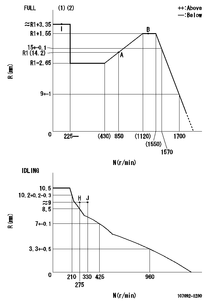
N:Pump speed
R:Rack position (mm)
(1)Torque cam stamping: T1
(2)Tolerance for racks not indicated: +-0.05mm.
----------
T1=AE66
----------
----------
T1=AE66
----------
Speed control lever angle
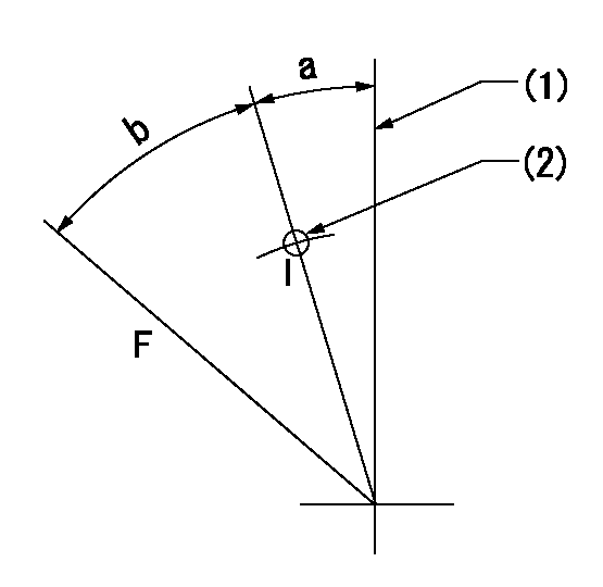
F:Full speed
I:Idle
(1)Stopper bolt setting
(2)Use the pin at R = aa
----------
aa=35mm
----------
a=2deg+-5deg b=37deg+-3deg
----------
aa=35mm
----------
a=2deg+-5deg b=37deg+-3deg
Stop lever angle
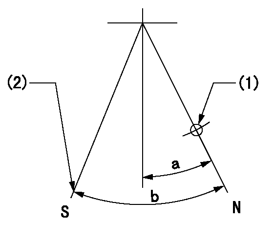
N:Pump normal
S:Stop the pump.
(1)Use the pin at R = aa
(2)Set the stopper screw so that speed = bb and the rack position = cc and confirm non-injection.
----------
aa=40mm bb=0r/min cc=1.5+-0.3mm
----------
a=12deg+-5deg b=44deg+-5deg
----------
aa=40mm bb=0r/min cc=1.5+-0.3mm
----------
a=12deg+-5deg b=44deg+-5deg
0000001301

(1)Pump vertical direction
(2)Position of flywheel's threaded hole at No 1 cylinder's beginning of injection
(3)B.T.D.C.: aa
(4)Pre-stroke: bb
----------
aa=7deg bb=5.1+-0.03mm
----------
a=(50deg)
----------
aa=7deg bb=5.1+-0.03mm
----------
a=(50deg)
0000001401

(1)Pointer
(2)Injection timing aligning mark
(3)Fly weight
(4)The actual shape and direction may be different from this illustration.
Operation sequence
1. Turn the prestroke actuator OFF.
2. Turn the camshaft as far as the No.1 cylinder's beginning of injection position.
3. Check that the pointer alignment mark of the injection pump and the alignment mark of the flywheel are matching.
4. If they are not matching, erase the alignment mark on the flywheel side, and stamp an alignment mark on the flywheel position that matches with the pointer side alignment mark.
5. Check again that the coupling's key groove position is in the No.1 cylinder's beginning of injection position.
----------
----------
----------
----------
0000001701

A : Stopper pin
B: Connector
----------
----------
----------
----------
0000001801

C:Shim
----------
----------
----------
----------
0000001901

A:Sealing position
B:Pre-stroke actuator
1. When installing the pre-stroke actuator on the pump, first tighten the installation bolts loosely, then move the actuator fully clockwise (viewed from the drive side).
Temporary tightening torque: 1 - 1.5 N.m (0.1 - 0.15 kgf.m)
2. Move the actuator in the counterclockwise direction when viewed from the drive side, and adjust so that it becomes the adjustment point of the adjustment value. Then tighten it.
Tightening torque: 7^9 N.m (0.7^0.9 kgf.m)
3. After prestroke actuator installation adjustment, simultaneously stamp both the actuator side and housing side.
----------
----------
----------
----------
0000002201 RACK SENSOR
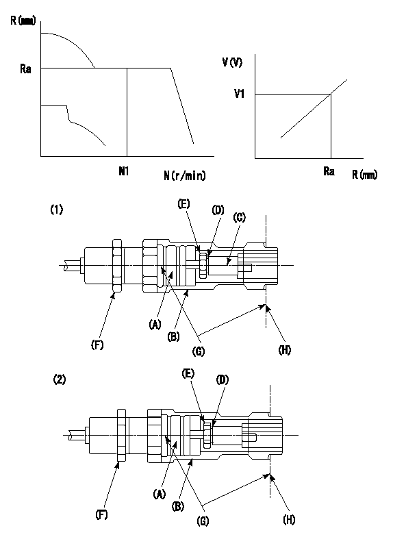
G:Red paint
H:Pump end face
P/N: part number of suitable shim
(1)Threaded type rack block
(2)Welded type rack block
Rack sensor adjustment
1. Threaded type rack sensor (-5*20, P type, no TICS rack limit).
(1)Screw in the bobbin (A) until it contacts the joint (B).
(2)Fix the pump lever.
(3)At speed N1 and rack position Ra, adjust the amount that the bobbin is screwed in so that the amp's output voltage is V1.
(4)Fix using the nut (F).
(5)Affix the caution plate to the upper part of the joint (B).
(6)Apply (G) at two places.
Connecting part between the joint (B) and the nut (F)
Connecting part between the end surface of the pump (H) and the joint (B)
2. Range for screw-in adjustment between the bobbin (A) and the joint (B) is 9 threads.
Screw in to the end from (the position where the bobbin (A) is rotated 9 turns).
Speed N1, rack position Ra, output voltage V1, rack sensor supply voltage 5+-0.01 (V)
----------
Ra=R1(14.2)+1.55mm N1=1400r/min V1=3+-0.01V
----------
----------
Ra=R1(14.2)+1.55mm N1=1400r/min V1=3+-0.01V
----------
Information:
Engine Performance
Poor vessel performance is traditionally believed to be the result of a lack (or loss) of engine performance, when in fact the engine is only one of numerous factors that influence the overall performance of a vessel. Several factors determine the power demand on an engine. The engine has no control over the demand made upon it by the vessel design, such as hull, prop and driveline design. These same factors also affect the amount of power available to perform additional work such as to drive auxiliary pumps.If you feel you have a vessel performance problem, first consider the impact of vessel design and condition, loads, propeller and driveline condition, etc. on power demand. Deterioration of vessel systems (cooling, air intake and exhaust, fuel tanks, etc.) can only lessen the engine's chance to produce power and vessel speed. In the case of poor fuel economy, the engine is not likely to be the cause without the presence of excessive exhaust smoke and/or a significant loss of power.If you feel you have a valid engine performance problem, contact an authorized Caterpillar marine engine servicing dealer for assistance. If your engine is under warranty then the Caterpillar warranty will cover the cost of resolving a valid engine performance deficiency. However, if the engine is not found at fault, all costs incurred will be the responsibility of the owner. Adjustment of the fuel system outside Caterpillar specified limits will not improve fuel efficiency and could result in damage to the engine.Your Caterpillar dealer can determine engine condition and check the engine's external systems using a diagnostic procedure called the Marine Engine Performance Analysis Report (PAR). (See next topic).Caterpillar engines are designed and manufactured using state-of-the-art technology to provide maximum fuel efficiency and performance in all applications. To insure optimum performance for the life of your engine, follow the recommended operation and preventive maintenance procedures described in this publication.Marine Engine Performance Analysis Report (PAR)
Today's marine user is concerned with performance, cost of operation and satisfactory engine life. Traditionally, vessel performance has been directly related to the propulsion engine, when in fact the engine is only one of numerous factors influencing the propulsion system.To verify the condition of the propulsion system, Caterpillar has developed the Marine Engine Performance Analysis Report (PAR) program. Marine Engine PAR is an in-vessel test procedure, performed and evaluated by Caterpillar certified Marine Analysts under normal or bollard operating conditions, comparing the performance of all marine engine systems to original factory test cell specifications.When Marine Engine PAR testing is conducted at Sea Trial, it can assure you of a quality installation that confirms hull, rudders, propeller, marine transmission, ventilation and cooling systems are all properly matched for optimum performance and fuel efficiency.Caterpillar additionally recommends regularly scheduled (see Maintenance Schedule) Marine Engine PAR analyses to maintain optimum performance. Periodic PAR analyses can define propulsion system deterioration and aid in fine tuning the maintenance, repair and overhaul schedules, which will provide you the most economical and efficient cost of operation.