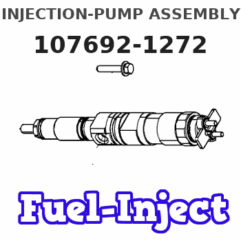
Information injection-pump assembly
BOSCH
9 400 612 086
9400612086
ZEXEL
107692-1272
1076921272
ISUZU
8943911093
8943911093

Rating:
Service parts 107692-1272 INJECTION-PUMP ASSEMBLY:
1.
_
5.
AUTOM. ADVANCE MECHANIS
9.
_
11.
Nozzle and Holder
8-94394-606-5
12.
Open Pre:MPa(Kqf/cm2)
21.6{220}
15.
NOZZLE SET
Include in #1:
107692-1272
as INJECTION-PUMP ASSEMBLY
Cross reference number
Zexel num
Bosch num
Firm num
Name
107692-1272
9 400 612 086
8943911093 ISUZU
INJECTION-PUMP ASSEMBLY
6HE1-TCN K 14CG INJECTION PUMP ASSY TICS MD-TI6 TICS
6HE1-TCN K 14CG INJECTION PUMP ASSY TICS MD-TI6 TICS
Information:
Stopping the engine immediately after it has been working under load can result in overheating and accelerated wear of the engine components. Follow the stopping procedures, outlined below, to allow the engine to cool. Excessive temperatures in the turbocharger center housing will cause oil coking problems.
Prior to stopping an engine that is being operated at low loads, run the engine at LOW IDLE for 30 seconds before stopping. If the engine is being operated at high load, then it should be run at LOW IDLE for five minutes to reduce and stabilize internal engine coolant and oil temperatures before stopping.Make sure the Engine Stopping procedure is understood. The engine may be shutdown in several ways. To manually stop the engine, refer to the following information and instructions.Emergency Stop Procedure
The Emergency Stop Pushbutton (ESPB) and Emergency stop controls are for EMERGENCY use ONLY. DO NOT use for normal stopping procedure. Emergency Stop controls should only be used when an emergency exists, and not used to routinely stop the engine. Do NOT start the engine until the problem necessitating the emergency stop has been located and corrected.
* Emergency stops may be made through the Emergency Stop Pushbutton (ESPB). If the need for emergency engine shutdown occurs, push the EMERGENCY STOP Pushbutton located on the control panel or the engine junction box. This will activate the air and/or fuel shutoffs. Reset the EMERGENCY STOP Pushbutton (pull out and rotate the button in the direction indicated on the button). Some EMERGENCY STOP Pushbuttons can be pulled out to reset, not requiring any rotation.Manual Stop Procedure
1. Reduce the engine speed to LOW IDLE. Shift the marine transmission to NEUTRAL and secure the vessel.2. Increase engine speed to no more than half engine speed for five minutes to cool the engine. Reduce engine speed to LOW IDLE. 3. Check the crankcase oil level while the engine is idling. Maintain the oil level between the ADD and FULL marks on the CHECK WITH ENGINE RUNNING or ENGINE AT LOW IDLE WITH OIL WARM side of the dipstick.4. Shift the marine transmission to FORWARD or REVERSE. Check the marine transmission oil level at ENGINE AT LOW IDLE WITH OIL WARM. Maintain oil level between the ADD and FULL marks on the dipstick. Shift the marine transmission back to NEUTRAL.5. The engine may be stopped by using one of the following engine mounted controls.Toggle Switch
Move OEM or customer supplied toggle switch to the OFF position to shut off the fuel shutoff solenoid.Manual Fuel Shutoff Lever (All Engines)
Do not use the emergency shutoff control for a normal stopping procedure. A manual shutdown shaft is provided to override the governor solenoid. This shutdown will only move the fuel control linkage to the fuel OFF position to starve the engine of fuel. It does not shut off the air inlet. The engine will coast to a stop. Be sure to secure any external system components that have been operating to support the engine operation.After Stopping the Engine
1. If freezing temperatures
Have questions with 107692-1272?
Group cross 107692-1272 ZEXEL
Isuzu
Isuzu
107692-1272
9 400 612 086
8943911093
INJECTION-PUMP ASSEMBLY
6HE1-TCN
6HE1-TCN