Information injection-pump assembly
ZEXEL
107692-1260
1076921260
ISUZU
8943906190
8943906190
Rating:
Cross reference number
ZEXEL
107692-1260
1076921260
ISUZU
8943906190
8943906190
Zexel num
Bosch num
Firm num
Name
Calibration Data:
Adjustment conditions
Test oil
1404 Test oil ISO4113 or {SAEJ967d}
1404 Test oil ISO4113 or {SAEJ967d}
Test oil temperature
degC
40
40
45
Nozzle and nozzle holder
105780-8250
Bosch type code
1 688 901 101
Nozzle
105780-0120
Bosch type code
1 688 901 990
Nozzle holder
105780-2190
Opening pressure
MPa
20.7
Opening pressure
kgf/cm2
211
Injection pipe
Outer diameter - inner diameter - length (mm) mm 8-3-600
Outer diameter - inner diameter - length (mm) mm 8-3-600
Overflow valve
131425-0520
Overflow valve opening pressure
kPa
255
221
289
Overflow valve opening pressure
kgf/cm2
2.6
2.25
2.95
Tester oil delivery pressure
kPa
255
255
255
Tester oil delivery pressure
kgf/cm2
2.6
2.6
2.6
PS/ACT control unit part no.
407980-2
24*
Digi switch no.
17
Direction of rotation (viewed from drive side)
Left L
Left L
Injection timing adjustment
Direction of rotation (viewed from drive side)
Left L
Left L
Injection order
1-5-3-6-
2-4
Pre-stroke
mm
5.1
5.07
5.13
Beginning of injection position
Governor side NO.1
Governor side NO.1
Difference between angles 1
Cal 1-5 deg. 60 59.75 60.25
Cal 1-5 deg. 60 59.75 60.25
Difference between angles 2
Cal 1-3 deg. 120 119.75 120.25
Cal 1-3 deg. 120 119.75 120.25
Difference between angles 3
Cal 1-6 deg. 180 179.75 180.25
Cal 1-6 deg. 180 179.75 180.25
Difference between angles 4
Cyl.1-2 deg. 240 239.75 240.25
Cyl.1-2 deg. 240 239.75 240.25
Difference between angles 5
Cal 1-4 deg. 300 299.75 300.25
Cal 1-4 deg. 300 299.75 300.25
Injection quantity adjustment
Adjusting point
-
Rack position
13.1
Pump speed
r/min
750
750
750
Average injection quantity
mm3/st.
102
100.4
103.6
Max. variation between cylinders
%
0
-2.5
2.5
Basic
*
Fixing the rack
*
PS407980-224*
V
2.25+-0.
01
PS407980-224*
mm
3.1+-0.0
5
Standard for adjustment of the maximum variation between cylinders
*
Injection quantity adjustment_02
Adjusting point
Z
Rack position
9.1+-0.5
Pump speed
r/min
420
420
420
Average injection quantity
mm3/st.
18.5
16.7
20.3
Max. variation between cylinders
%
0
-14
14
Fixing the rack
*
PS407980-224*
V
V1+0.05+
-0.01
PS407980-224*
mm
5+-0.03
Standard for adjustment of the maximum variation between cylinders
*
Remarks
Refer to items regarding the pre-stroke actuator
Refer to items regarding the pre-stroke actuator
Injection quantity adjustment_03
Adjusting point
A
Rack position
R1(13.1)
Pump speed
r/min
750
750
750
Average injection quantity
mm3/st.
102
101
103
Basic
*
Fixing the lever
*
Boost pressure
kPa
60
60
Boost pressure
mmHg
450
450
PS407980-224*
V
2.25+-0.
01
PS407980-224*
mm
3.1+-0.0
5
Boost compensator adjustment
Pump speed
r/min
300
300
300
Rack position
R2-1.9
Boost pressure
kPa
17.3
16
18.6
Boost pressure
mmHg
130
120
140
Boost compensator adjustment_02
Pump speed
r/min
300
300
300
Rack position
R2(R1-0.
35)
Boost pressure
kPa
46.7
46.7
46.7
Boost pressure
mmHg
350
350
350
0000001601
CU407980-224*
*
Actuator retarding type
*
Supply voltage
V
24
23.5
24.5
Ambient temperature
degC
23
18
28
Pre-stroke
mm
2
1.95
2.05
Output voltage
V
2.83
2.82
2.84
Adjustment
*
_02
CU407980-224*
*
Supply voltage
V
24
23.5
24.5
Ambient temperature
degC
23
18
28
Pre-stroke
mm
5.1
5.07
5.13
Output voltage
V
1.2
1
1.4
Confirmation
*
Remarks
Output voltage V1
Output voltage V1
_03
CU407980-224*
*
Supply voltage
V
24
23.5
24.5
Ambient temperature
degC
23
18
28
Output voltage
V
3.05
3.05
Confirmation of operating range
*
Test data Ex:
Governor adjustment
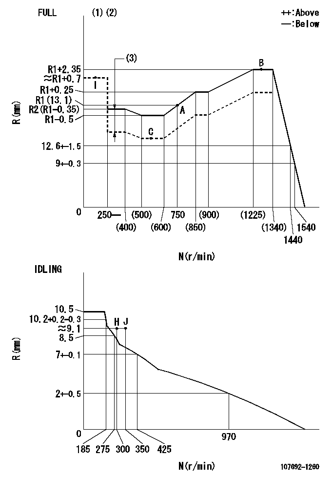
N:Pump speed
R:Rack position (mm)
(1)Torque cam stamping: T1
(2)Tolerance for racks not indicated: +-0.05mm.
(3)Boost compensator stroke: BCL
----------
T1=AB48 BCL=1.9+-0.1mm
----------
----------
T1=AB48 BCL=1.9+-0.1mm
----------
Speed control lever angle
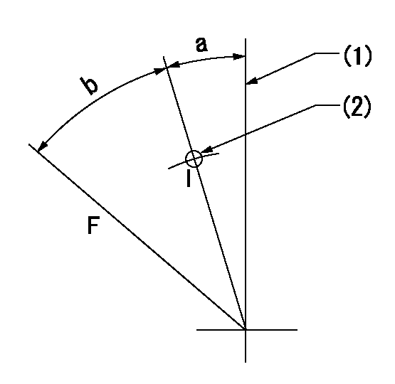
F:Full speed
I:Idle
(1)Stopper bolt set position 'H'
(2)Use the pin at R = aa
----------
aa=35mm
----------
a=2deg+-5deg b=34deg+-3deg
----------
aa=35mm
----------
a=2deg+-5deg b=34deg+-3deg
Stop lever angle
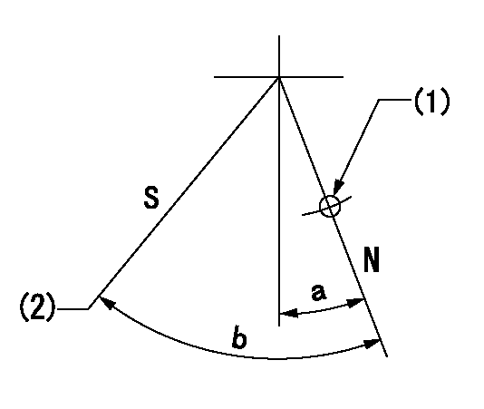
N:Pump normal
S:Stop the pump.
(1)Use the pin at R = aa
(2)Set the stopper bolt at speed = bb and rack position = cc (non-injection rack position). Confirm non-injection.
----------
aa=40mm bb=0r/min cc=1.5+-0.3mm
----------
a=12deg+-5deg b=44deg+-5deg
----------
aa=40mm bb=0r/min cc=1.5+-0.3mm
----------
a=12deg+-5deg b=44deg+-5deg
0000001301

(1)Pump vertical direction
(2)Position of flywheel's threaded hole at No 1 cylinder's beginning of injection
(3)B.T.D.C.: aa
(4)Pre-stroke: bb
----------
aa=4deg bb=5.1+-0.03mm
----------
a=(50deg)
----------
aa=4deg bb=5.1+-0.03mm
----------
a=(50deg)
0000001401

(1)Pointer
(2)Injection timing aligning mark
(3)Fly weight
(4)The actual shape and direction may be different from this illustration.
Operation sequence
1. Turn the prestroke actuator OFF.
2. Turn the camshaft as far as the No.1 cylinder's beginning of injection position.
3. Check that the pointer alignment mark of the injection pump and the alignment mark of the flywheel are matching.
4. If they are not matching, erase the alignment mark on the flywheel side, and stamp an alignment mark on the flywheel position that matches with the pointer side alignment mark.
5. Check again that the coupling's key groove position is in the No.1 cylinder's beginning of injection position.
----------
----------
----------
----------
0000001701

A : Stopper pin
B: Connector
----------
----------
----------
----------
0000001801

C:Shim
----------
----------
----------
----------
0000001901

A:Sealing position
B:Pre-stroke actuator
1. When installing the pre-stroke actuator on the pump, first tighten the installation bolts loosely, then move the actuator fully clockwise (viewed from the drive side).
Temporary tightening torque: 1 - 1.5 N.m (0.1 - 0.15 kgf.m)
2. Move the actuator in the counterclockwise direction when viewed from the drive side, and adjust so that it becomes the adjustment point of the adjustment value. Then tighten it.
Tightening torque: 7^9 N.m (0.7^0.9 kgf.m)
3. After prestroke actuator installation adjustment, simultaneously stamp both the actuator side and housing side.
----------
----------
----------
----------
0000002201 RACK SENSOR

(VR) measurement voltage
(I) Part number of the control unit
(G) Apply red paint.
(H): End surface of the pump
1. Rack sensor adjustment (-0620)
(1)Fix the speed control lever at the full position
(2)Set the speed to N1 r/min.
(If the boost compensator is provided, apply boost pressure.)
(3)Adjust the bobbin (A) so that the rack sensor's output voltage is VR+-0.01.
(4)At that time, rack position must be Ra.
(5)Apply G at two places.
Connecting part between the joint (B) and the nut (F)
Connecting part between the joint (B) and the end surface of the pump (H)
----------
N1=1250r/min Ra=R1(13.1)+2.35mm
----------
----------
N1=1250r/min Ra=R1(13.1)+2.35mm
----------
Information:
Lubricant Viscosity Chart
Commercial Oils
Failure to follow the commercial oil recommendations can cause shortened engine life due to piston carbon deposits, liner bore polish and/or abnormally higher increasing oil consumption.API CC and CD oils are unacceptable in this Caterpillar diesel engine.
* API specifications CF-4, CF-4/SH or CF-4/SGThe oil specifications above provide guidelines for the selection of commercial products. They may require shortened oil change intervals as determined by close monitoring of oil condition with Scheduled Oil Sampling (S O S). The same viscosity grades are recommended for commercial oils as for CAT oils.Lubricant Total Base Number (TBN)
New engine oil must have a TBN of 20 times (for Precombustion Chamber engines) and 10 times (for direct injection engines) the percent fuel sulfur as measured by ASTM (American Society if Testing Materials) D2896 method. Refer to the Fuel Specifications in this manual for additional information.Caterpillar DI Engines Only
Additional Notes
The percentage of sulfur in the fuel will affect the engine oil recommendations. For fuel sulfur effects, the ASTM D2896 procedure can be used to evaluate the residual neutralization properties of an engine oil. The sulfur products formation depends on the fuel sulfur content, oil formulation, crankcase blowby, engine operating conditions and ambient temperature.The fuel sulfur neutralization of today's new oil formulations along with direct injection (DI) system engines are more effective. Field results indicate that direct injection combustion (DI) systems and the oils now recommended for these engines will operate at an oil TBN equal to 10 times the fuel sulfur above 0.5% and using API CF-4 oils. Caterpillar requirements reflect this value of 10 times for DI engines.Caterpillar still maintains 20 times TBN value for precombustion chamber (PC) engines when using API CD, CE or CF-4 oil when related to fuel sulfur above 0.5%. Used oil analysis should be a part of the overall program to provide the assurance that a particular engine installation with all its parameters (engine, oil, operation, maintenance and fuel) are under control. Engines built prior to 1990 can continue to use DEO-CD single grade viscosity oil or commercial oils provided the engine operates to user satisfaction. Consult with your Caterpillar dealer for the latest lubrication recommendations.Synthetic Base Stock Oils (SPC)
The performance characteristics of the oil depends on the base oil and the additives. The additives in the oil will vary according to the properties of the base oil and the environment in which the oil will perform its function.Synthetic base stock oils are acceptable for use in Caterpillar engines if these oils meet the performance requirements specified for a particular compartment. The performance requirements for engines using synthetic oils is API CF-4 with API CE as an alternative.The use of a synthetic base stock oil does NOT allow extension of the oil drain period simply because of the use of synthetic oil. Any drain period extension must be validated by S O S (oil analysis and test evaluation) to ensure no excessive component wear occurs in a particular application.The synthetic oils have naturally low pour points