Information injection-pump assembly
ZEXEL
107692-1250
1076921250
ISUZU
8943906180
8943906180

Rating:
Cross reference number
ZEXEL
107692-1250
1076921250
ISUZU
8943906180
8943906180
Zexel num
Bosch num
Firm num
Name
Calibration Data:
Adjustment conditions
Test oil
1404 Test oil ISO4113 or {SAEJ967d}
1404 Test oil ISO4113 or {SAEJ967d}
Test oil temperature
degC
40
40
45
Nozzle and nozzle holder
105780-8250
Bosch type code
1 688 901 101
Nozzle
105780-0120
Bosch type code
1 688 901 990
Nozzle holder
105780-2190
Opening pressure
MPa
20.7
Opening pressure
kgf/cm2
211
Injection pipe
Outer diameter - inner diameter - length (mm) mm 8-3-600
Outer diameter - inner diameter - length (mm) mm 8-3-600
Overflow valve
131425-0520
Overflow valve opening pressure
kPa
255
221
289
Overflow valve opening pressure
kgf/cm2
2.6
2.25
2.95
Tester oil delivery pressure
kPa
255
255
255
Tester oil delivery pressure
kgf/cm2
2.6
2.6
2.6
PS/ACT control unit part no.
407980-2
24*
Digi switch no.
17
Direction of rotation (viewed from drive side)
Left L
Left L
Injection timing adjustment
Direction of rotation (viewed from drive side)
Left L
Left L
Injection order
1-5-3-6-
2-4
Pre-stroke
mm
5.1
5.07
5.13
Beginning of injection position
Governor side NO.1
Governor side NO.1
Difference between angles 1
Cal 1-5 deg. 60 59.75 60.25
Cal 1-5 deg. 60 59.75 60.25
Difference between angles 2
Cal 1-3 deg. 120 119.75 120.25
Cal 1-3 deg. 120 119.75 120.25
Difference between angles 3
Cal 1-6 deg. 180 179.75 180.25
Cal 1-6 deg. 180 179.75 180.25
Difference between angles 4
Cyl.1-2 deg. 240 239.75 240.25
Cyl.1-2 deg. 240 239.75 240.25
Difference between angles 5
Cal 1-4 deg. 300 299.75 300.25
Cal 1-4 deg. 300 299.75 300.25
Injection quantity adjustment
Adjusting point
-
Rack position
14.4
Pump speed
r/min
750
750
750
Average injection quantity
mm3/st.
120
118.4
121.6
Max. variation between cylinders
%
0
-2.5
2.5
Basic
*
Fixing the rack
*
PS407980-224*
V
2.25+-0.
01
PS407980-224*
mm
3.1+-0.0
5
Standard for adjustment of the maximum variation between cylinders
*
Injection quantity adjustment_02
Adjusting point
Z
Rack position
9+-0.5
Pump speed
r/min
425
425
425
Average injection quantity
mm3/st.
19
17.7
20.3
Max. variation between cylinders
%
0
-14
14
Fixing the rack
*
PS407980-224*
V
V1+0.05+
-0.01
PS407980-224*
mm
5+-0.03
Standard for adjustment of the maximum variation between cylinders
*
Remarks
Refer to items regarding the pre-stroke actuator
Refer to items regarding the pre-stroke actuator
Injection quantity adjustment_03
Adjusting point
A
Rack position
R1(14.4)
Pump speed
r/min
750
750
750
Average injection quantity
mm3/st.
120
119
121
Basic
*
Fixing the lever
*
Boost pressure
kPa
61.3
61.3
Boost pressure
mmHg
460
460
PS407980-224*
V
2.25+-0.
01
PS407980-224*
mm
3.1+-0.0
5
Boost compensator adjustment
Pump speed
r/min
300
300
300
Rack position
R2-2.7
Boost pressure
kPa
17.3
16
18.6
Boost pressure
mmHg
130
120
140
Boost compensator adjustment_02
Pump speed
r/min
300
300
300
Rack position
R2(R1-0.
55)
Boost pressure
kPa
48
48
48
Boost pressure
mmHg
360
360
360
0000001601
CU407980-224*
*
Actuator retarding type
*
Supply voltage
V
24
23.5
24.5
Ambient temperature
degC
23
18
28
Pre-stroke
mm
2
1.95
2.05
Output voltage
V
2.83
2.82
2.84
Adjustment
*
_02
CU407980-224*
*
Supply voltage
V
24
23.5
24.5
Ambient temperature
degC
23
18
28
Pre-stroke
mm
5.1
5.07
5.13
Output voltage
V
1.2
1
1.4
Confirmation
*
Remarks
Output voltage V1
Output voltage V1
_03
CU407980-224*
*
Supply voltage
V
24
23.5
24.5
Ambient temperature
degC
23
18
28
Output voltage
V
3.05
3.05
Confirmation of operating range
*
Test data Ex:
Governor adjustment
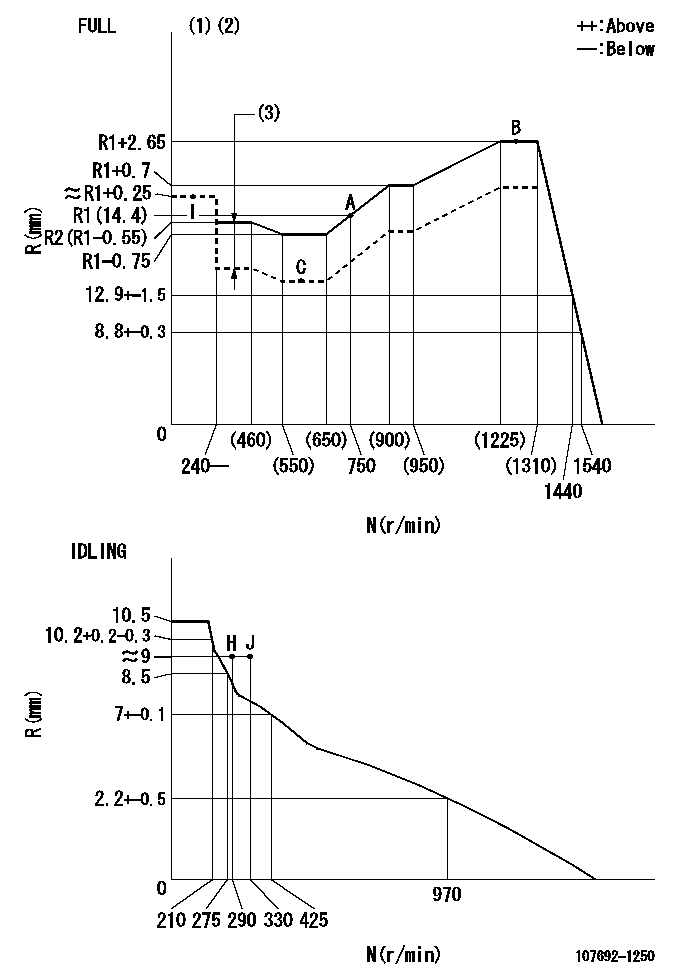
N:Pump speed
R:Rack position (mm)
(1)Torque cam stamping: T1
(2)Tolerance for racks not indicated: +-0.05mm.
(3)Boost compensator stroke: BCL
----------
T1=AB47 BCL=2.7+-0.1mm
----------
----------
T1=AB47 BCL=2.7+-0.1mm
----------
Speed control lever angle
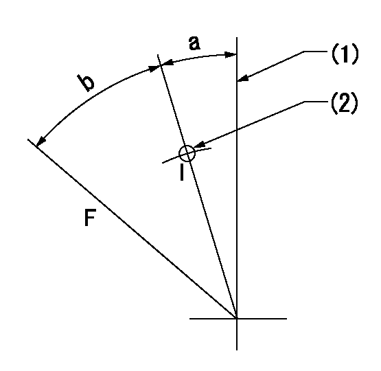
F:Full speed
I:Idle
(1)Stopper bolt set position 'H'
(2)Use the pin at R = aa
----------
aa=35mm
----------
a=2deg+-5deg b=32.5deg+-3deg
----------
aa=35mm
----------
a=2deg+-5deg b=32.5deg+-3deg
Stop lever angle
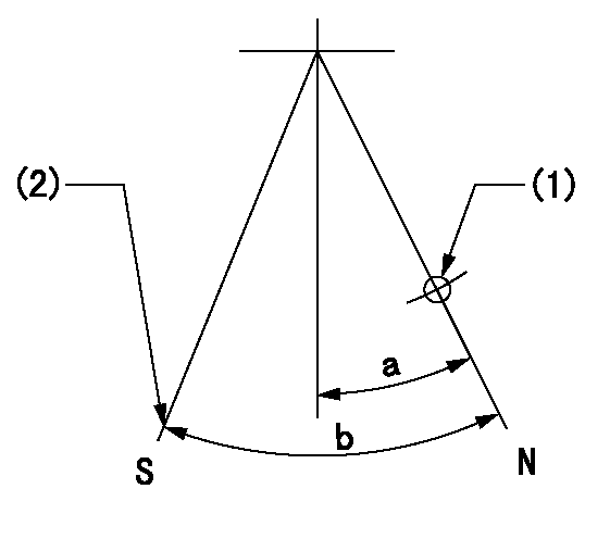
N:Pump normal
S:Stop the pump.
(1)Use the pin at R = aa
(2)Set the stopper bolt at speed = bb and rack position = cc (non-injection rack position). Confirm non-injection.
----------
aa=40mm bb=0r/min cc=1.5+-0.3mm
----------
a=12deg+-5deg b=44deg+-5deg
----------
aa=40mm bb=0r/min cc=1.5+-0.3mm
----------
a=12deg+-5deg b=44deg+-5deg
0000001301

(1)Pump vertical direction
(2)Position of flywheel's threaded hole at No 1 cylinder's beginning of injection
(3)B.T.D.C.: aa
(4)Pre-stroke: bb
----------
aa=1deg bb=5.1+-0.03mm
----------
a=(50deg)
----------
aa=1deg bb=5.1+-0.03mm
----------
a=(50deg)
0000001401

(1)Pointer
(2)Injection timing aligning mark
(3)Fly weight
(4)The actual shape and direction may be different from this illustration.
Operation sequence
1. Turn the prestroke actuator OFF.
2. Turn the camshaft as far as the No.1 cylinder's beginning of injection position.
3. Check that the pointer alignment mark of the injection pump and the alignment mark of the flywheel are matching.
4. If they are not matching, erase the alignment mark on the flywheel side, and stamp an alignment mark on the flywheel position that matches with the pointer side alignment mark.
5. Check again that the coupling's key groove position is in the No.1 cylinder's beginning of injection position.
----------
----------
----------
----------
0000001701

A : Stopper pin
B: Connector
----------
----------
----------
----------
0000001801

C:Shim
----------
----------
----------
----------
0000001901

A:Sealing position
B:Pre-stroke actuator
1. When installing the pre-stroke actuator on the pump, first tighten the installation bolts loosely, then move the actuator fully clockwise (viewed from the drive side).
Temporary tightening torque: 1 - 1.5 N.m (0.1 - 0.15 kgf.m)
2. Move the actuator in the counterclockwise direction when viewed from the drive side, and adjust so that it becomes the adjustment point of the adjustment value. Then tighten it.
Tightening torque: 7^9 N.m (0.7^0.9 kgf.m)
3. After prestroke actuator installation adjustment, simultaneously stamp both the actuator side and housing side.
----------
----------
----------
----------
0000002201 RACK SENSOR

(VR) measurement voltage
(I) Part number of the control unit
(G) Apply red paint.
(H): End surface of the pump
1. Rack sensor adjustment (-0620)
(1)Fix the speed control lever at the full position
(2)Set the speed to N1 r/min.
(If the boost compensator is provided, apply boost pressure.)
(3)Adjust the bobbin (A) so that the rack sensor's output voltage is VR+-0.01.
(4)At that time, rack position must be Ra.
(5)Apply G at two places.
Connecting part between the joint (B) and the nut (F)
Connecting part between the joint (B) and the end surface of the pump (H)
----------
N1=1250r/min Ra=R1(14.4)+2.65mm
----------
----------
N1=1250r/min Ra=R1(14.4)+2.65mm
----------
Information:
When it is necessary to remove a component on an angle, remember that the capacity of an eyebolt is less as the angle between the supporting members and the object becomes less than 90 degrees. Eyebolts and brackets should never be bent and should only be loaded in tension.
Use a hoist to remove heavy components. Lift the engine by using an adjustable lifting beam. All supporting members (chains and cables) should be parallel to each other, and as near perpendicular as possible to the top of the object being lifted.Some removals require the use of lifting fixtures to obtain proper balance and to provide safe handling. To remove the engine ONLY, use the two lifting eyes equipped with the engine.Lifting eyes are designed for the engine arrangement as is. Alterations to lifting eyes and/or arrangement weight make the lifting devices and eyes obsolete. If you make alterations, you are responsible for providing adequate lifting devices.See your Caterpillar dealer or vessel OEM for information regarding fixtures for proper lifting of your complete engine power package.Engine and Marine Transmission Lifting
To remove the engine only or the engine and marine transmission together, use the two lifting eyes on the engine.Marine Transmission Lifting
To remove the marine transmission only, use the four permanent eyebolts in the marine transmission housing.If a component resists removal, check to be certain all nuts and bolts have been removed and that an adjacent part is not interfering.Engine Storage
These instructions give procedures and recommendations that will keep the possibility of damage at a minimum when engines are in storage for one year or less.If the engine will not be or has not been started for several weeks, the lubricating oil will drain from the cylinder walls and piston rings.If an engine remains out of service and its use is not immediately planned, special precautions should be taken. Rust can form on the cylinder liner surface, which will increase engine wear and may result in shorter engine life. To prevent this problem from becoming excessive, be sure all lubrication recommendations mentioned in the Maintenance Schedule are completed.After one year, a complete protection procedure must be followed if the engine is kept in storage longer. Refer to Storage Procedures For Caterpillar Products, SEHS9031 for more detailed information on engine storage.If freezing temperatures are expected, check the cooling system for adequate protection against freezing. A fifty/fifty solution of Caterpillar (permanent-type) Antifreeze and approved water will give protection to -29°C (-20°F).If it will be impossible to start the engine periodically, consult your Caterpillar dealer for instructions to prepare your engine for longer storage periods.If an engine remains out of service and its use is not immediately planned, special precautions should be taken. Refer to Storage Procedures For Caterpillar Products, SEHS9031 for more detailed information on engine storage.Recommendations After Engine Storage
1. Remove all outside protective covers, and any tape or grease used for protection.2. Drain the VCI oil1 and engine oil mixture from the engine. If the oil has been in the engine for