Information injection-pump assembly
ZEXEL
107692-1240
1076921240
Rating:
Cross reference number
ZEXEL
107692-1240
1076921240
Zexel num
Bosch num
Firm num
Name
107692-1240
INJECTION-PUMP ASSEMBLY
Calibration Data:
Adjustment conditions
Test oil
1404 Test oil ISO4113 or {SAEJ967d}
1404 Test oil ISO4113 or {SAEJ967d}
Test oil temperature
degC
40
40
45
Nozzle and nozzle holder
105780-8250
Bosch type code
1 688 901 101
Nozzle
105780-0120
Bosch type code
1 688 901 990
Nozzle holder
105780-2190
Opening pressure
MPa
20.7
Opening pressure
kgf/cm2
211
Injection pipe
Outer diameter - inner diameter - length (mm) mm 8-3-600
Outer diameter - inner diameter - length (mm) mm 8-3-600
Overflow valve
131425-0520
Overflow valve opening pressure
kPa
255
221
289
Overflow valve opening pressure
kgf/cm2
2.6
2.25
2.95
Tester oil delivery pressure
kPa
255
255
255
Tester oil delivery pressure
kgf/cm2
2.6
2.6
2.6
PS/ACT control unit part no.
407910-3
03*
Selector switch no.
00
PS/ACT control unit part no.
407980-2
24*
Digi switch no.
11
Direction of rotation (viewed from drive side)
Left L
Left L
Injection timing adjustment
Direction of rotation (viewed from drive side)
Left L
Left L
Injection order
1-5-3-6-
2-4
Pre-stroke
mm
1.9
1.87
1.93
Beginning of injection position
Governor side NO.1
Governor side NO.1
Difference between angles 1
Cal 1-5 deg. 60 59.75 60.25
Cal 1-5 deg. 60 59.75 60.25
Difference between angles 2
Cal 1-3 deg. 120 119.75 120.25
Cal 1-3 deg. 120 119.75 120.25
Difference between angles 3
Cal 1-6 deg. 180 179.75 180.25
Cal 1-6 deg. 180 179.75 180.25
Difference between angles 4
Cyl.1-2 deg. 240 239.75 240.25
Cyl.1-2 deg. 240 239.75 240.25
Difference between angles 5
Cal 1-4 deg. 300 299.75 300.25
Cal 1-4 deg. 300 299.75 300.25
Injection quantity adjustment
Adjusting point
-
Rack position
13.3
Pump speed
r/min
750
750
750
Average injection quantity
mm3/st.
102.5
100.9
104.1
Max. variation between cylinders
%
0
-2.5
2.5
Basic
*
Fixing the rack
*
PS407980-224*
V
1.88+-0.
01
PS407980-224*
mm
3.2+-0.0
5
PS407910-303*
V
1.88+-0.
01
PS407910-303*
mm
3.2+-0.0
5
Standard for adjustment of the maximum variation between cylinders
*
Injection quantity adjustment_02
Adjusting point
Z
Rack position
9.1+-0.5
Pump speed
r/min
410
410
410
Average injection quantity
mm3/st.
18.5
16.7
20.3
Max. variation between cylinders
%
0
-14
14
Fixing the rack
*
PS407980-224*
V
V1-0.05+
-0.01
PS407980-224*
mm
4.9+-0.0
3
PS407910-303*
V
V1-0.05+
-0.01
PS407910-303*
mm
4.9+-0.0
3
Standard for adjustment of the maximum variation between cylinders
*
Remarks
Refer to items regarding the pre-stroke actuator
Refer to items regarding the pre-stroke actuator
Injection quantity adjustment_03
Adjusting point
A
Rack position
R1(13.3)
Pump speed
r/min
750
750
750
Average injection quantity
mm3/st.
102.5
101.5
103.5
Basic
*
Fixing the lever
*
Boost pressure
kPa
60
60
Boost pressure
mmHg
450
450
PS407980-224*
V
1.88+-0.
01
PS407980-224*
mm
3.2+-0.0
5
PS407910-303*
V
1.88+-0.
01
PS407910-303*
mm
3.2+-0.0
5
Boost compensator adjustment
Pump speed
r/min
300
300
300
Rack position
R2-1.9
Boost pressure
kPa
17.3
16
18.6
Boost pressure
mmHg
130
120
140
Boost compensator adjustment_02
Pump speed
r/min
300
300
300
Rack position
R2(R1-0.
35)
Boost pressure
kPa
46.7
46.7
46.7
Boost pressure
mmHg
350
350
350
0000001601
CU407980-224*
*
Actuator advancing type
*
Supply voltage
V
12
11.5
12.5
Ambient temperature
degC
23
18
28
Pre-stroke
mm
5
4.95
5.05
Output voltage
V
2.83
2.82
2.84
Adjustment
*
Remarks
Output voltage V1
Output voltage V1
_02
CU407980-224*
*
Supply voltage
V
12
11.5
12.5
Ambient temperature
degC
23
18
28
Pre-stroke
mm
1.9
1.87
1.93
Output voltage
V
1.2
1
1.4
Confirmation
*
_03
CU407980-224*
*
Supply voltage
V
12
11.5
12.5
Ambient temperature
degC
23
18
28
Output voltage
V
3.05
3.05
Confirmation of operating range
*
_04
CU407910-303*
*
Actuator advancing type
*
Supply voltage
V
12
11.5
12.5
Ambient temperature
degC
23
18
28
Pre-stroke
mm
5
4.95
5.05
Output voltage
V
2.83
2.82
2.84
Adjustment
*
Remarks
Output voltage V1
Output voltage V1
_05
CU407910-303*
*
Supply voltage
V
12
11.5
12.5
Ambient temperature
degC
23
18
28
Pre-stroke
mm
1.9
1.87
1.93
Output voltage
V
1.2
1
1.4
Confirmation
*
_06
CU407910-303*
*
Supply voltage
V
12
11.5
12.5
Ambient temperature
degC
23
18
28
Output voltage
V
3.05
3.05
Confirmation of operating range
*
Test data Ex:
Governor adjustment
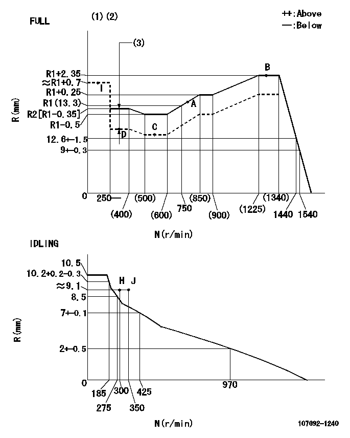
N:Pump speed
R:Rack position (mm)
(1)Torque cam stamping: T1
(2)Tolerance for racks not indicated: +-0.05mm.
(3)Boost compensator stroke: BCL
----------
T1=AB48 BCL=1.9+-0.1mm
----------
----------
T1=AB48 BCL=1.9+-0.1mm
----------
Speed control lever angle
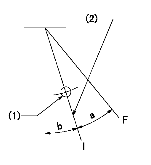
F:Full speed
I:Idle
(1)Use the hole at R = aa
(2)Stopper bolt setting
----------
aa=40mm
----------
a=32deg+-3deg b=1deg+-5deg
----------
aa=40mm
----------
a=32deg+-3deg b=1deg+-5deg
Stop lever angle
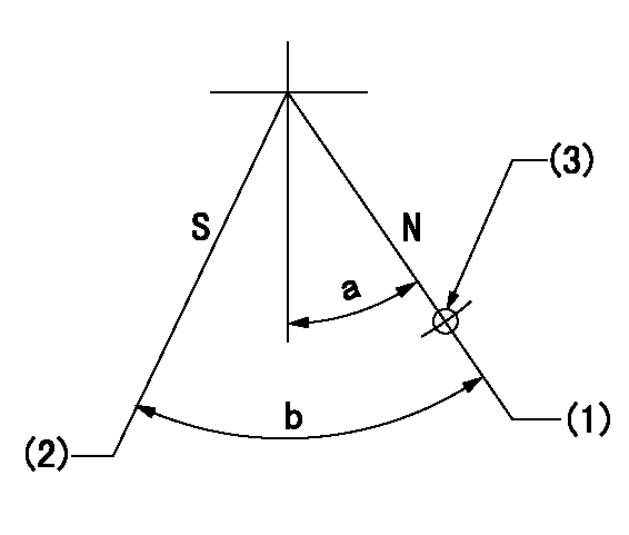
N:Pump normal
S:Stop the pump.
(1)-
(2)Set the stopper bolt at speed = aa and rack position = bb and confirm non-injection.
(3)Use the pin above R = cc
----------
aa=0r/min bb=1.5+-0.3mm cc=40mm
----------
a=12deg+-5deg b=44deg+-5deg
----------
aa=0r/min bb=1.5+-0.3mm cc=40mm
----------
a=12deg+-5deg b=44deg+-5deg
0000001301

(1)Pump vertical direction
(2)Position of flywheel's threaded hole at No 1 cylinder's beginning of injection
(3)B.T.D.C.: aa
(4)Pre-stroke: bb
----------
aa=22deg bb=1.9+-0.03mm
----------
a=(60deg)
----------
aa=22deg bb=1.9+-0.03mm
----------
a=(60deg)
0000001401

(1)Pointer
(2)Injection timing aligning mark
(3)Fly weight
(4)The actual shape and direction may be different from this illustration.
Operation sequence
1. Turn the prestroke actuator OFF.
2. Turn the camshaft as far as the No.1 cylinder's beginning of injection position.
3. Check that the pointer alignment mark of the injection pump and the alignment mark of the flywheel are matching.
4. If they are not matching, erase the alignment mark on the flywheel side, and stamp an alignment mark on the flywheel position that matches with the pointer side alignment mark.
5. Check again that the coupling's key groove position is in the No.1 cylinder's beginning of injection position.
----------
----------
----------
----------
0000001701
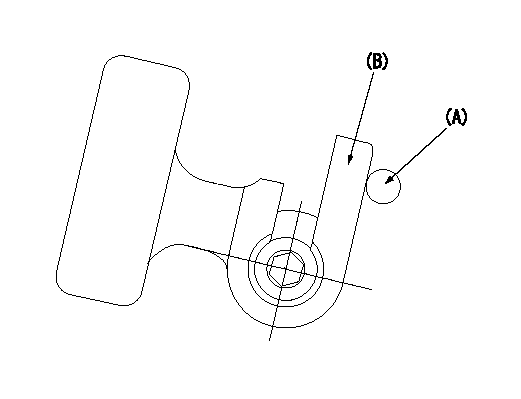
A : Stopper pin
B: Connector
----------
----------
----------
----------
0000001801

C:Shim
----------
----------
----------
----------
0000001901

A:Sealing position
B:Pre-stroke actuator
1. When installing the pre-stroke actuator on the pump, first tighten the installation bolts loosely, then move the actuator fully clockwise (viewed from the drive side).
Temporary tightening torque: 1 - 1.5 N.m (0.1 - 0.15 kgf.m)
2. Move the actuator in the counterclockwise direction when viewed from the drive side, and adjust so that it becomes the adjustment point of the adjustment value. Then tighten it.
Tightening torque: 7^9 N.m (0.7^0.9 kgf.m)
3. After prestroke actuator installation adjustment, simultaneously stamp both the actuator side and housing side.
----------
----------
----------
----------
0000002201 RACK SENSOR

(VR) measurement voltage
(I) Part number of the control unit
(G) Apply red paint.
(H): End surface of the pump
1. Rack sensor adjustment (-0620)
(1)Fix the speed control lever at the full position
(2)Set the speed to N1 r/min.
(If the boost compensator is provided, apply boost pressure.)
(3)Adjust the bobbin (A) so that the rack sensor's output voltage is VR+-0.01.
(4)At that time, rack position must be Ra.
(5)Apply G at two places.
Connecting part between the joint (B) and the nut (F)
Connecting part between the joint (B) and the end surface of the pump (H)
----------
N1=1250r/min Ra=R1(13.3)+2.35mm
----------
----------
N1=1250r/min Ra=R1(13.3)+2.35mm
----------
Information:
North America Only:When a problem arises concerning the sale, operation or service of your engine, or the marine vessel OEM, it will normally be handled by the dealer in your area. The service facility nearest you can be located 24 hours-a-day by calling In U.S. and Canada 1 (800) 447-4986.Your satisfaction is a primary concern to Caterpillar and its dealers. To assure your complete satisfaction, we suggest the following steps be followed should you have a problem that has not been handled to your satisfaction. Step One- Discuss your problem with a member of management from the dealership. Step Two- When it appears that your problem cannot be readily resolved at the dealer level without additional assistance, use the above telephone number and ask to talk to a Field Service Coordinator. Regular Monday through Friday business hours are from 8:00 a.m. to 4:30 p.m. Central Standard Time (CST). Step Three If you are still not satisfied, present the engine matter in writing to:Caterpillar Inc.
Manager, Customer Service, Engine Division
Mossville Bldg. A
P.O. Box 600
Mossville, Illinois 61552-0600
When contacting the Manager, Customer Service, please keep in mind that your problem will likely be resolved at the dealership, using their facilities, equipment and personnel. Therefore, it is suggested that you follow the above steps in sequence when experiencing a problem. Outside North America:If a problem arises outside North America and cannot be resolved at the dealer level, contact the appropriate Caterpillar subsidiary office. Mid and South America (except Brazil):Caterpillar Americas Co.
100 NE Adams Street
Peoria, Illinois 61629 U.S.A.
Phone: 309-675-5876
Brazil:Caterpillar Brasil S.A.
04795-Av. Das Nacoes Unidas,
22.540 (S. Amaro)
Mail Address: Caixa Postal, 8239
01.000-Sao Paulo-SP-Brazil
Phone: 247-1011-5919-1100
Cable Address: CATERPILLAR SP. BRAZIL
Telex No.: 391-01122824 & 391-01121496
Europe, Africa, and Middle East:Caterpillar Overseas S.A./Power Systems
YA50 76, Route de Frontenex
P.O. Box 456
1211 Geneva 6
Switzerland
Cable Address: CATOVERSEA
Telex No.: 413323
Phone: (022) 737 4444
Telecopier: (022) 737 4984
Australia and New Zealand:Caterpillar of Australia Ltd.
1 Sharps Road
Private Mail Bag 4
Tullamarine, Victoria 3043
Australia
Telex: AA30240
Cable: CATERPILLAR MELB
Phone: (03) 3399333
Far East (except Japan and Australia):Caterpillar Far East Limited
28th Floor, Sun Hung Kai Centre
30 Harbour Road
G.P.O. Box 3069
Wanchai, Hong Kong
Cable Address: CATFAREAST HKG
Telex No.: HX73305 CFEL
Phone: 5-8326333
Japan:Caterpillar Mitsubishi Ltd.
3700, Tana, Sagamihara-shi
Kanagawa-ken, 229
Japan
Telex No.: 2872-261CM HAJ
Cable Address: CATERBISHICO SAGAMIHARA
Phone: Sagamihara (0427) 62-1121
Have questions with 107692-1240?
Group cross 107692-1240 ZEXEL
Isuzu
107692-1240
INJECTION-PUMP ASSEMBLY