Information injection-pump assembly
ZEXEL
107692-0990
1076920990

Rating:
Cross reference number
ZEXEL
107692-0990
1076920990
Zexel num
Bosch num
Firm num
Name
107692-0990
INJECTION-PUMP ASSEMBLY
Calibration Data:
Adjustment conditions
Test oil
1404 Test oil ISO4113 or {SAEJ967d}
1404 Test oil ISO4113 or {SAEJ967d}
Test oil temperature
degC
40
40
45
Nozzle and nozzle holder
105780-8250
Bosch type code
1 688 901 101
Nozzle
105780-0120
Bosch type code
1 688 901 990
Nozzle holder
105780-2190
Opening pressure
MPa
20.7
Opening pressure
kgf/cm2
211
Injection pipe
Outer diameter - inner diameter - length (mm) mm 8-3-600
Outer diameter - inner diameter - length (mm) mm 8-3-600
Overflow valve
131425-0520
Overflow valve opening pressure
kPa
255
221
289
Overflow valve opening pressure
kgf/cm2
2.6
2.25
2.95
Tester oil delivery pressure
kPa
255
255
255
Tester oil delivery pressure
kgf/cm2
2.6
2.6
2.6
RED3 control unit part number
407910-3
960
RED3 rack sensor specifications
mm
19
PS/ACT control unit part no.
407980-2
24*
Digi switch no.
14
Direction of rotation (viewed from drive side)
Right R
Right R
Injection timing adjustment
Direction of rotation (viewed from drive side)
Right R
Right R
Injection order
1-4-2-6-
3-5
Pre-stroke
mm
5.1
5.07
5.13
Beginning of injection position
Drive side NO.1
Drive side NO.1
Difference between angles 1
Cal 1-4 deg. 60 59.75 60.25
Cal 1-4 deg. 60 59.75 60.25
Difference between angles 2
Cyl.1-2 deg. 120 119.75 120.25
Cyl.1-2 deg. 120 119.75 120.25
Difference between angles 3
Cal 1-6 deg. 180 179.75 180.25
Cal 1-6 deg. 180 179.75 180.25
Difference between angles 4
Cal 1-3 deg. 240 239.75 240.25
Cal 1-3 deg. 240 239.75 240.25
Difference between angles 5
Cal 1-5 deg. 300 299.75 300.25
Cal 1-5 deg. 300 299.75 300.25
Injection quantity adjustment
Rack position
(16.6)
Vist
V
1.36
1.36
1.36
Pump speed
r/min
1400
1400
1400
Average injection quantity
mm3/st.
136
135
137
Max. variation between cylinders
%
0
-4
4
Basic
*
PS407980-224*
V
2.25+-0.
01
PS407980-224*
mm
3.1+-0.0
5
Injection quantity adjustment_02
Rack position
(6.6)
Vist
V
2.9
2.8
3
Pump speed
r/min
490
490
490
Average injection quantity
mm3/st.
18
16.2
19.8
Max. variation between cylinders
%
0
-10
10
PS407980-224*
V
V1+0.05+
-0.01
PS407980-224*
mm
5+-0.03
Remarks
Refer to items regarding the pre-stroke actuator
Refer to items regarding the pre-stroke actuator
0000001201
CU407980-224*
*
Actuator retarding type
*
Supply voltage
V
24
23.5
24.5
Ambient temperature
degC
23
18
28
Pre-stroke
mm
2
1.95
2.05
Output voltage
V
2.83
2.82
2.84
Adjustment
*
_02
CU407980-224*
*
Supply voltage
V
24
23.5
24.5
Ambient temperature
degC
23
18
28
Pre-stroke
mm
5.1
5.07
5.13
Output voltage
V
1.2
1
1.4
Confirmation
*
Remarks
Output voltage V1
Output voltage V1
_03
CU407980-224*
*
Supply voltage
V
24
23.5
24.5
Ambient temperature
degC
23
18
28
Output voltage
V
3.05
3.05
Confirmation of operating range
*
Test data Ex:
Speed control lever angle

N:Pump normal
S:Stop the pump.
(1)Rack position = aa
(2)Rack position bb
----------
aa=20mm bb=1mm
----------
a=27deg+-5deg b=37deg+-5deg
----------
aa=20mm bb=1mm
----------
a=27deg+-5deg b=37deg+-5deg
0000000901

(1)Pump vertical direction
(2)Coupling's key groove position at No 1 cylinder's beginning of injection
(3)Pre-stroke: aa
(4)-
----------
aa=5.1+-0.03mm
----------
a=(20deg)
----------
aa=5.1+-0.03mm
----------
a=(20deg)
Stop lever angle

(1)Pointer
(2)Injection timing aligning mark
(3)Fly weight
(4)The actual shape and direction may be different from this illustration.
Operation sequence
1. Turn the prestroke actuator OFF.
2. Turn the camshaft as far as the No.1 cylinder's beginning of injection position.
3. Check that the pointer alignment mark of the injection pump and the alignment mark of the flywheel are matching.
4. If they are not matching, erase the alignment mark on the flywheel side, and stamp an alignment mark on the flywheel position that matches with the pointer side alignment mark.
5. Check again that the coupling's key groove position is in the No.1 cylinder's beginning of injection position.
----------
----------
----------
----------
0000001301
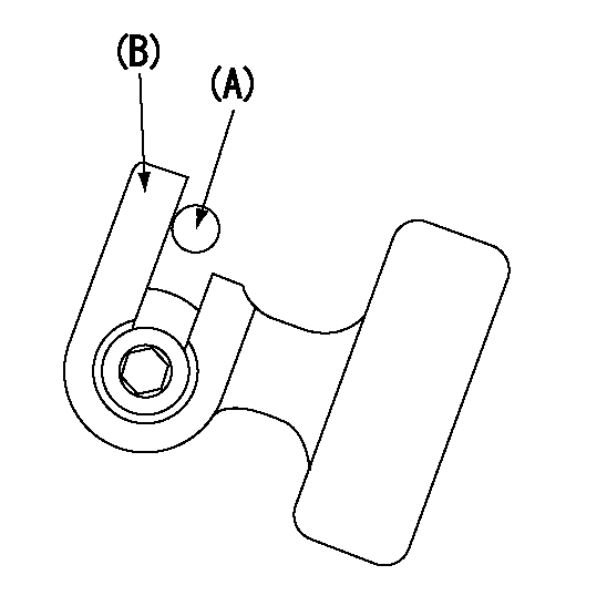
A : Stopper pin
B: Connector
----------
----------
----------
----------
0000001401
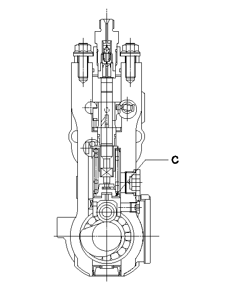
C:Shim
----------
----------
----------
----------
0000001501

A:Sealing position
B:Pre-stroke actuator
1. When installing the pre-stroke actuator on the pump, first tighten the installation bolts loosely, then move the actuator fully counterclockwise (viewed from the drive side).
Temporary tightening torque: 1 - 1.5 N.m (0.1 - 0.15 kgf.m)
2. Move the actuator in the clockwise direction when viewed from the drive side, and adjust so that it becomes the adjustment point of the adjustment value. Then tighten it.
Tightening torque: 7^9 N.m (0.7^0.9 kgf.m)
3. After prestroke actuator installation adjustment, simultaneously stamp both the actuator side and housing side.
----------
----------
----------
----------
0000001701

(Rs) rack sensor specifications
(C/U) control unit part number
(V) Rack sensor output voltage
(R) Rack position (mm)
1. Confirming governor output characteristics (rack 19 mm, span 6 mm)
(1)When the output voltages of the rack sensor are V1 and V2, check that the rack positions R1 and R2 in the table above are satisfied.
----------
----------
----------
----------
Information:
Possible Causes/Corrections
Air Or Water In Fuel System
With air in the fuel system, the engine will normally be difficult to start, run rough, and release a large amount of white smoke. If the engine will not start, loosen a fuel injection line nut at the through the head adapter and crank the engine until fuel comes out. Tighten the fuel line nut. Start the engine. If the engine does not run smooth or releases a large amount of white smoke, loosen the fuel line nuts one at a time at the through the head adapters until the fuel that comes out is free of air. Tighten the fuel line nuts. If the air cannot be removed in this way, put 35 kPa (5 psi) of air pressure to the fuel tank.
Do not use more than 55 kPa (8 psi) of air pressure in the fuel tank or damage to the tank may result.
Check for leaks at the connection between the fuel tank and the fuel transfer pump. If leaks are found, tighten the connections or replace the lines. If there are no visual leaks, remove the fuel supply line from the tank and connect it to an outside furl supply. If this corrects the problem, the suction line (standpipe) inside the fuel tank has a leak.Water in the fuel can cause rough running and possible fuel system damage.Valve Adjustment Not Correct
Check and make necessary adjustments as in Testing And Adjusting Section of the Service Manual. Intake valve lash is 0.38 mm (.015 in) and exhaust valve lash is 0.64 mm (.025 in). Also check for a bent or broken push rod.Defective Fuel Nozzle(s)
Find a defective nozzle by running engine at the rpm where it runs rough. Loosen the fuel line nut at the through the head adapter enough to stop fuel supply to that cylinder. Each cylinder must be checked this way. If a cylinder is found where loosening of the nut makes no difference in the rough running, test the nozzle for that cylinder. To test a nozzle, remove the nozzle from the engine and test as in Testing and Adjusting Section of this Service Manual.Fuel Leakage From Fuel Injection Line Nut
Tighten nut to 40 7 N m (30 5 lb ft). Again check for leakage. Be sure to check fuel injection lines inside valve cover base.Defective Fuel Injection Pump
An injection pump can have a good fuel flow coming from it but cause rough running because of slow timing that is caused by wear on the bottom end of the plunger. See the Testing and Adjusting Section in this Service Manual for the correct specifications and procedure to check plungers and lifters.Fuel pumps which are severely scored from debris can cause rough running but fuel dilution usually occurs before horsepower is affected.Low installation torque on the fuel pump retaining nut can cause misfire, rough running and low power.Fuel Has A High "Cloud Point"
In cold weather operation this condition should be checked first. The fuel "cloud point"
Have questions with 107692-0990?
Group cross 107692-0990 ZEXEL
Nissan-Diesel
Nissan-Diesel
Nissan-Diesel
Nissan-Diesel
Nissan-Diesel
Nissan-Diesel
Nissan-Diesel
Nissan-Diesel
107692-0990
INJECTION-PUMP ASSEMBLY