Information injection-pump assembly
ZEXEL
107692-0900
1076920900
Rating:
Cross reference number
ZEXEL
107692-0900
1076920900
Zexel num
Bosch num
Firm num
Name
107692-0900
INJECTION-PUMP ASSEMBLY
Calibration Data:
Adjustment conditions
Test oil
1404 Test oil ISO4113 or {SAEJ967d}
1404 Test oil ISO4113 or {SAEJ967d}
Test oil temperature
degC
40
40
45
Nozzle and nozzle holder
105780-8250
Bosch type code
1 688 901 101
Nozzle
105780-0120
Bosch type code
1 688 901 990
Nozzle holder
105780-2190
Opening pressure
MPa
20.7
Opening pressure
kgf/cm2
211
Injection pipe
Outer diameter - inner diameter - length (mm) mm 8-3-600
Outer diameter - inner diameter - length (mm) mm 8-3-600
Overflow valve
131425-0520
Overflow valve opening pressure
kPa
255
221
289
Overflow valve opening pressure
kgf/cm2
2.6
2.25
2.95
Tester oil delivery pressure
kPa
255
255
255
Tester oil delivery pressure
kgf/cm2
2.6
2.6
2.6
PS/ACT control unit part no.
407910-3
03*
Selector switch no.
01
PS/ACT control unit part no.
407980-2
24*
Digi switch no.
15
Direction of rotation (viewed from drive side)
Right R
Right R
Injection timing adjustment
Direction of rotation (viewed from drive side)
Right R
Right R
Injection order
1-4-2-6-
3-5
Pre-stroke
mm
5.1
5.07
5.13
Beginning of injection position
Drive side NO.1
Drive side NO.1
Difference between angles 1
Cal 1-4 deg. 60 59.75 60.25
Cal 1-4 deg. 60 59.75 60.25
Difference between angles 2
Cyl.1-2 deg. 120 119.75 120.25
Cyl.1-2 deg. 120 119.75 120.25
Difference between angles 3
Cal 1-6 deg. 180 179.75 180.25
Cal 1-6 deg. 180 179.75 180.25
Difference between angles 4
Cal 1-3 deg. 240 239.75 240.25
Cal 1-3 deg. 240 239.75 240.25
Difference between angles 5
Cal 1-5 deg. 300 299.75 300.25
Cal 1-5 deg. 300 299.75 300.25
Injection quantity adjustment
Adjusting point
-
Rack position
15.3
Pump speed
r/min
1300
1300
1300
Average injection quantity
mm3/st.
129.5
127.5
131.5
Max. variation between cylinders
%
0
-4
4
Basic
*
Fixing the rack
*
PS407980-224*
V
2.25+-0.
01
PS407980-224*
mm
3.1+-0.0
5
PS407910-303*
V
2.25+-0.
01
PS407910-303*
mm
3.1+-0.0
5
Standard for adjustment of the maximum variation between cylinders
*
Injection quantity adjustment_02
Adjusting point
Z
Rack position
8+-0.5
Pump speed
r/min
440
440
440
Average injection quantity
mm3/st.
10.6
8.8
12.4
Max. variation between cylinders
%
0
-10
10
Fixing the rack
*
PS407980-224*
V
V1+0.05+
-0.01
PS407980-224*
mm
5+-0.03
PS407910-303*
V
V1+0.05+
-0.01
PS407910-303*
mm
5+-0.03
Standard for adjustment of the maximum variation between cylinders
*
Remarks
Refer to items regarding the pre-stroke actuator
Refer to items regarding the pre-stroke actuator
Injection quantity adjustment_03
Adjusting point
A
Rack position
R1(15.3)
Pump speed
r/min
1300
1300
1300
Average injection quantity
mm3/st.
129.5
128.5
130.5
Basic
*
Fixing the lever
*
Boost pressure
kPa
36
36
Boost pressure
mmHg
270
270
PS407980-224*
V
2.25+-0.
01
PS407980-224*
mm
3.1+-0.0
5
PS407910-303*
V
2.25+-0.
01
PS407910-303*
mm
3.1+-0.0
5
Injection quantity adjustment_04
Adjusting point
B
Rack position
R1-1.9
Pump speed
r/min
800
800
800
Average injection quantity
mm3/st.
123.5
119.5
127.5
Fixing the lever
*
Boost pressure
kPa
36
36
Boost pressure
mmHg
270
270
PS407980-224*
V
2.25+-0.
01
PS407980-224*
mm
3.1+-0.0
5
PS407910-303*
V
2.25+-0.
01
PS407910-303*
mm
3.1+-0.0
5
Injection quantity adjustment_05
Adjusting point
C
Rack position
R2-1.65
Pump speed
r/min
350
350
350
Average injection quantity
mm3/st.
72
68
76
Fixing the lever
*
Boost pressure
kPa
0
0
0
Boost pressure
mmHg
0
0
0
PS407980-224*
V
2.25+-0.
01
PS407980-224*
mm
3.1+-0.0
5
PS407910-303*
V
2.25+-0.
01
PS407910-303*
mm
3.1+-0.0
5
Boost compensator adjustment
Pump speed
r/min
350
350
350
Rack position
R2-1.65
Boost pressure
kPa
5.3
4
6.6
Boost pressure
mmHg
40
30
50
Boost compensator adjustment_02
Pump speed
r/min
350
350
350
Rack position
R2(R1-3.
3)
Boost pressure
kPa
22.7
22.7
22.7
Boost pressure
mmHg
170
170
170
0000001601
CU407980-224*
*
Actuator retarding type
*
Supply voltage
V
12
11.5
12.5
Ambient temperature
degC
23
18
28
Pre-stroke
mm
2
1.95
2.05
Output voltage
V
2.83
2.82
2.84
Adjustment
*
_02
CU407980-224*
*
Supply voltage
V
12
11.5
12.5
Ambient temperature
degC
23
18
28
Pre-stroke
mm
5.1
5.07
5.13
Output voltage
V
1.2
1
1.4
Confirmation
*
Remarks
Output voltage V1
Output voltage V1
_03
CU407980-224*
*
Supply voltage
V
12
11.5
12.5
Ambient temperature
degC
23
18
28
Output voltage
V
3.05
3.05
Confirmation of operating range
*
_04
CU407910-303*
*
Actuator retarding type
*
Supply voltage
V
12
11.5
12.5
Ambient temperature
degC
23
18
28
Pre-stroke
mm
2
1.95
2.05
Output voltage
V
2.83
2.82
2.84
Adjustment
*
_05
CU407910-303*
*
Supply voltage
V
12
11.5
12.5
Ambient temperature
degC
23
18
28
Pre-stroke
mm
5.1
5.07
5.13
Output voltage
V
1.2
1
1.4
Confirmation
*
Remarks
Output voltage V1
Output voltage V1
_06
CU407910-303*
*
Supply voltage
V
12
11.5
12.5
Ambient temperature
degC
23
18
28
Output voltage
V
3.05
3.05
Confirmation of operating range
*
Test data Ex:
Governor adjustment
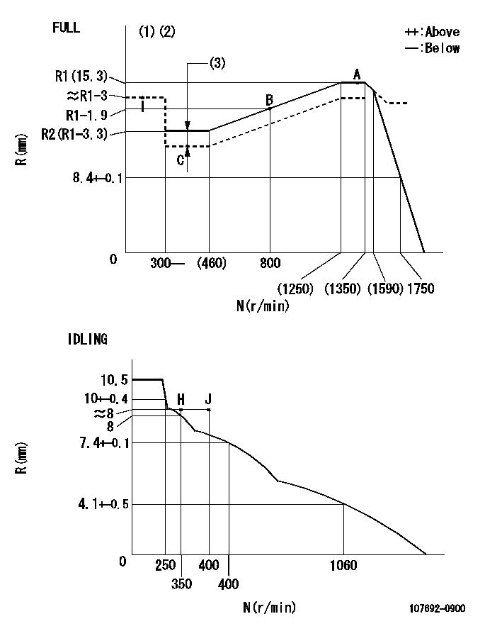
N:Pump speed
R:Rack position (mm)
(1)Torque cam stamping: T1
(2)Tolerance for racks not indicated: +-0.05mm.
(3)Boost compensator stroke: BCL
----------
T1=AF56 BCL=1.65+-0.1mm
----------
----------
T1=AF56 BCL=1.65+-0.1mm
----------
Speed control lever angle

F:Full speed
I:Idle
(1)Use the hole at R = aa
(2)Stopper bolt set position 'H'
----------
aa=93.5mm
----------
a=18.5deg+-5deg b=34.5deg+-3deg
----------
aa=93.5mm
----------
a=18.5deg+-5deg b=34.5deg+-3deg
Stop lever angle
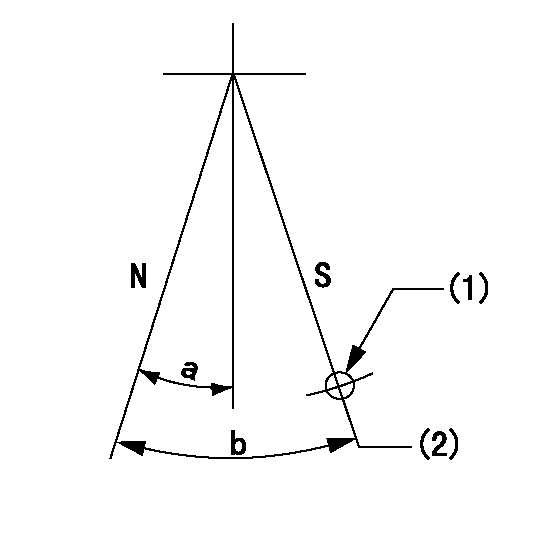
N:Pump normal
S:Stop the pump.
(1)Use the pin at R = aa
(2)Set the stopper bolt so that rack position = bb (speed = cc)
----------
aa=37mm bb=1.5+-0.3mm cc=0r/min
----------
a=20deg+-5deg b=45deg+-5deg
----------
aa=37mm bb=1.5+-0.3mm cc=0r/min
----------
a=20deg+-5deg b=45deg+-5deg
0000001301

(1)Pump vertical direction
(2)Coupling's key groove position at No 1 cylinder's beginning of injection
(3)Pre-stroke: aa
(4)-
----------
aa=5.1+-0.03mm
----------
a=(20deg)
----------
aa=5.1+-0.03mm
----------
a=(20deg)
0000001401

(1)Pointer
(2)Injection timing aligning mark
(3)Fly weight
(4)The actual shape and direction may be different from this illustration.
Operation sequence
1. Turn the prestroke actuator OFF.
2. Turn the camshaft as far as the No.1 cylinder's beginning of injection position.
3. Check that the pointer alignment mark of the injection pump and the alignment mark of the flywheel are matching.
4. If they are not matching, erase the alignment mark on the flywheel side, and stamp an alignment mark on the flywheel position that matches with the pointer side alignment mark.
5. Check again that the coupling's key groove position is in the No.1 cylinder's beginning of injection position.
----------
----------
----------
----------
0000001701
A : Stopper pin
B: Connector
----------
----------
----------
----------
0000001801
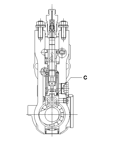
C:Shim
----------
----------
----------
----------
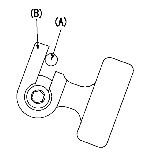
0000001901

A:Sealing position
B:Pre-stroke actuator
1. When installing the pre-stroke actuator on the pump, first tighten the installation bolts loosely, then move the actuator fully counterclockwise (viewed from the drive side).
Temporary tightening torque: 1 - 1.5 N.m (0.1 - 0.15 kgf.m)
2. Move the actuator in the clockwise direction when viewed from the drive side, and adjust so that it becomes the adjustment point of the adjustment value. Then tighten it.
Tightening torque: 7^9 N.m (0.7^0.9 kgf.m)
3. After prestroke actuator installation adjustment, simultaneously stamp both the actuator side and housing side.
----------
----------
----------
----------
0000002201 RACK SENSOR

(VR) measurement voltage
(I) Part number of the control unit
(G) Apply red paint.
(H): End surface of the pump
1. Rack sensor adjustment (-0620)
(1)Fix the speed control lever at the full position
(2)Set the speed to N1 r/min.
(If the boost compensator is provided, apply boost pressure.)
(3)Adjust the bobbin (A) so that the rack sensor's output voltage is VR+-0.01.
(4)At that time, rack position must be Ra.
(5)Apply G at two places.
Connecting part between the joint (B) and the nut (F)
Connecting part between the joint (B) and the end surface of the pump (H)
----------
N1=1300r/min Ra=R1(15.3)mm
----------
----------
N1=1300r/min Ra=R1(15.3)mm
----------
0000002301 ACS
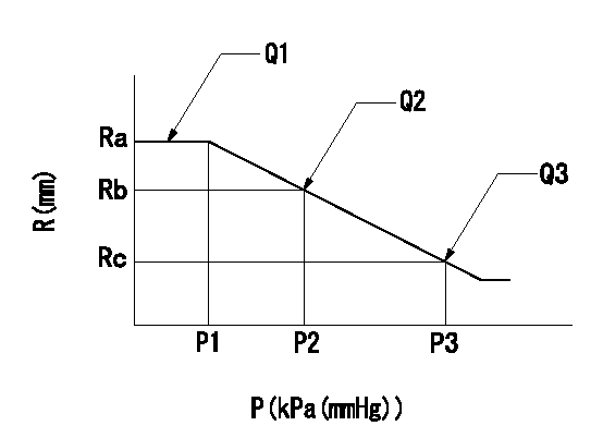
(P) Absolute pressure
(R) Rack position (mm)
1. Adjustment of the aneroid compensator
(1)Screw in the aneroid compensator body and attach the pushrod to the compensator lever so that the performance in the above graph can be obtained. The control lever must be at the full set position N = N1.
----------
N1=1300r/min
----------
Ra=R1(15.3)mm Rb=- Rc=R1-0.55mm P1=(93.3)+-2.7kPa((700)+-20mmHg) P2=- P3=61.6+-0.7kPa(462+-5mmHg) Q1=129.5+-1cm3/1000st Q2=- Q3=(120.5)cm3/1000st
----------
N1=1300r/min
----------
Ra=R1(15.3)mm Rb=- Rc=R1-0.55mm P1=(93.3)+-2.7kPa((700)+-20mmHg) P2=- P3=61.6+-0.7kPa(462+-5mmHg) Q1=129.5+-1cm3/1000st Q2=- Q3=(120.5)cm3/1000st
Information:
Start By:a. remove oil pumpb. remove oil pan plate
Keep all parts clean from contaminants. Contaminants put into the system may cause rapid wear and shortened component life.
1. Remove No. 1, 3, 5 and 7 main bearing caps (1). Remove the lower halves of the main bearings from the main bearing caps.
If the crankshaft is turned in the wrong direction, the tab on the bearing will be pushed between the crankshaft and the bearing area in the cylinder block. This can result in damage to the cylinder block and/or the crankshaft.
2. Install tool (A) in the hole in the crankshaft journal, and turn the crankshaft to remove the upper halves of main bearings (2).3. Remove crankshaft thrust bearings (3). Install the main bearings dry when the clearance checks are made. Put clean engine oil on the main bearings for final assembly.
Make sure the upper and lower halves of the main bearings are installed so the bearing tabs fit into the notch in the cylinder block and the main bearing caps.
4. Use tool (A), and install new upper halves of main bearings (2) in the cylinder block. Install new lower halves of main bearings (2) in main bearing caps (1).
When the bearing clearance is checked and the engine is in an upright position (vertical position with cylinder head on top), the crankshaft will have to be lifted up and held against the upper halves of the main bearings to get a correct measurement with the Plastigage. The Plastigage will not hold the weight of the crankshaft and give a correct indication. If the engine is in a horizontal position, it is not necessary to hold the crankshaft up. Do not turn the crankshaft when the Plastigage is in position to check clearances.
For complete details concerning measuring bearing clearances, see Engine Bearings And Crankshafts, Form No. SEBD0531.5. Check the main bearing clearance with Plastigage (B) as follows:a. Put a piece of Plastigage (B) on the crankshaft journals as shown.
Make sure the part number on the main bearing cap is toward the front of the engine and the number on the main bearing cap is the same as the number on the cylinder block on the left side of each main bearing cap.
b. Put main bearing caps (1) in position in the engine. Put 2P2506 Thread Lubricant on the bolt threads and the face of the washers, and install the bolts. Tighten the bolts to a torque of 40 4 N m (30 3 lb ft).c. Put a mark on each bolt and main bearing cap; then tighten the bolts 90° more.d. Remove the main bearing caps, and measure the Plastigage to find the bearing clearance. The main bearing clearance for new bearings must be 0.076 to 0.165 mm (.0030 to .0065 in). Maximum permissible clearance with used bearings is 0.25 mm (.010 in). 6. Put clean oil on the thrust bearing, and install a new thrust bearing for the rear main bearing. Install the thrust bearing with the identification
Have questions with 107692-0900?
Group cross 107692-0900 ZEXEL
107692-0900
INJECTION-PUMP ASSEMBLY