Information injection-pump assembly
BOSCH
F 019 Z10 231
f019z10231
ZEXEL
107691-7030
1076917030

Rating:
Service parts 107691-7030 INJECTION-PUMP ASSEMBLY:
1.
_
7.
COUPLING PLATE
9.
_
11.
Nozzle and Holder
12.
Open Pre:MPa(Kqf/cm2)
21.6(220)
15.
NOZZLE SET
Include in #1:
107691-7030
as INJECTION-PUMP ASSEMBLY
Cross reference number
BOSCH
F 019 Z10 231
f019z10231
ZEXEL
107691-7030
1076917030
Zexel num
Bosch num
Firm num
Name
Calibration Data:
Adjustment conditions
Test oil
1404 Test oil ISO4113 or {SAEJ967d}
1404 Test oil ISO4113 or {SAEJ967d}
Test oil temperature
degC
40
40
45
Nozzle and nozzle holder
105780-8250
Bosch type code
1 688 901 101
Nozzle
105780-0120
Bosch type code
1 688 901 990
Nozzle holder
105780-2190
Opening pressure
MPa
20.7
Opening pressure
kgf/cm2
211
Injection pipe
Outer diameter - inner diameter - length (mm) mm 8-3-600
Outer diameter - inner diameter - length (mm) mm 8-3-600
Overflow valve
131425-0520
Overflow valve opening pressure
kPa
255
221
289
Overflow valve opening pressure
kgf/cm2
2.6
2.25
2.95
Tester oil delivery pressure
kPa
255
255
255
Tester oil delivery pressure
kgf/cm2
2.6
2.6
2.6
RED3 control unit part number
407910-3
960
RED3 rack sensor specifications
mm
19
PS/ACT control unit part no.
407980-2
24*
Digi switch no.
17
Direction of rotation (viewed from drive side)
Left L
Left L
Injection timing adjustment
Direction of rotation (viewed from drive side)
Left L
Left L
Injection order
1-5-3-6-
2-4
Pre-stroke
mm
5.1
5.07
5.13
Beginning of injection position
Governor side NO.1
Governor side NO.1
Difference between angles 1
Cal 1-5 deg. 60 59.75 60.25
Cal 1-5 deg. 60 59.75 60.25
Difference between angles 2
Cal 1-3 deg. 120 119.75 120.25
Cal 1-3 deg. 120 119.75 120.25
Difference between angles 3
Cal 1-6 deg. 180 179.75 180.25
Cal 1-6 deg. 180 179.75 180.25
Difference between angles 4
Cyl.1-2 deg. 240 239.75 240.25
Cyl.1-2 deg. 240 239.75 240.25
Difference between angles 5
Cal 1-4 deg. 300 299.75 300.25
Cal 1-4 deg. 300 299.75 300.25
Injection quantity adjustment
Rack position
(12.5)
Vist
V
1.98
1.98
1.98
Pump speed
r/min
800
800
800
Average injection quantity
mm3/st.
140
139
141
Max. variation between cylinders
%
0
-3
3
Basic
*
PS407980-224*
V
2.25+-0.
01
PS407980-224*
mm
3.1+-0.0
5
Injection quantity adjustment_02
Rack position
(6.6)
Vist
V
2.9
2.8
3
Pump speed
r/min
395
395
395
Average injection quantity
mm3/st.
16.5
14.7
18.3
Max. variation between cylinders
%
0
-15
15
PS407980-224*
V
V1+0.05+
-0.01
PS407980-224*
mm
5+-0.03
Remarks
Refer to items regarding the pre-stroke actuator
Refer to items regarding the pre-stroke actuator
Governor adjustment
Pump speed
r/min
1050--
Advance angle
deg.
0
0
0
Remarks
Start
Start
Governor adjustment_02
Pump speed
r/min
1000
Advance angle
deg.
0
-0.5
0
Governor adjustment_03
Pump speed
r/min
1075
Advance angle
deg.
-1.5
-2
-1
Remarks
Finish
Finish
0000001201
CU407980-224*
*
Actuator retarding type
*
Supply voltage
V
24
23.5
24.5
Ambient temperature
degC
23
18
28
Pre-stroke
mm
2
1.95
2.05
Output voltage
V
2.83
2.82
2.84
Adjustment
*
_02
CU407980-224*
*
Supply voltage
V
24
23.5
24.5
Ambient temperature
degC
23
18
28
Pre-stroke
mm
5.1
5.07
5.13
Output voltage
V
1.2
1
1.4
Confirmation
*
Remarks
Output voltage V1
Output voltage V1
_03
CU407980-224*
*
Supply voltage
V
24
23.5
24.5
Ambient temperature
degC
23
18
28
Output voltage
V
3.05
3.05
Confirmation of operating range
*
Test data Ex:
Speed control lever angle
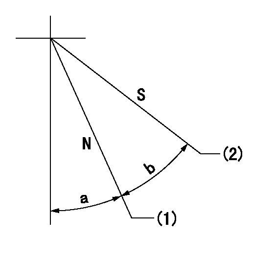
N:Pump normal
S:Stop the pump.
(1)Rack position = aa
(2)Rack position bb
----------
aa=20mm bb=1mm
----------
a=22deg+-5deg b=37deg+-5deg
----------
aa=20mm bb=1mm
----------
a=22deg+-5deg b=37deg+-5deg
0000000901

(1)Pump vertical direction
(2)Coupling's key groove position at No 1 cylinder's beginning of injection
(3)B.T.D.C.: aa
(4)Pre-stroke: bb
----------
aa=2deg bb=5.1+-0.03mm
----------
a=(2deg)
----------
aa=2deg bb=5.1+-0.03mm
----------
a=(2deg)
Stop lever angle

(1)Pointer
(2)Injection timing aligning mark
(3)Fly weight
(4)The actual shape and direction may be different from this illustration.
Operation sequence
1. Turn the prestroke actuator OFF.
2. Turn the camshaft as far as the No.1 cylinder's beginning of injection position.
3. Check that the pointer alignment mark of the injection pump and the alignment mark of the flywheel are matching.
4. If they are not matching, erase the alignment mark on the flywheel side, and stamp an alignment mark on the flywheel position that matches with the pointer side alignment mark.
5. Check again that the coupling's key groove position is in the No.1 cylinder's beginning of injection position.
----------
----------
----------
----------
0000001301

A : Stopper pin
B: Connector
----------
----------
----------
----------
0000001401

C:Shim
----------
----------
----------
----------
0000001501

A:Sealing position
B:Pre-stroke actuator
1. When installing the pre-stroke actuator on the pump, first tighten the installation bolts loosely, then move the actuator fully clockwise (viewed from the drive side).
Temporary tightening torque: 1 - 1.5 N.m (0.1 - 0.15 kgf.m)
2. Move the actuator in the counterclockwise direction when viewed from the drive side, and adjust so that it becomes the adjustment point of the adjustment value. Then tighten it.
Tightening torque: 7^9 N.m (0.7^0.9 kgf.m)
3. After prestroke actuator installation adjustment, simultaneously stamp both the actuator side and housing side.
----------
----------
----------
----------
0000001701

(Rs) rack sensor specifications
(C/U) control unit part number
(V) Rack sensor output voltage
(R) Rack position (mm)
1. Confirming governor output characteristics (rack 19 mm, span 6 mm)
(1)When the output voltages of the rack sensor are V1 and V2, check that the rack positions R1 and R2 in the table above are satisfied.
----------
----------
----------
----------
0000001901 RACK SENSOR

(VR) measurement voltage
(I) Part number of the control unit
(G) Apply red paint.
(H): End surface of the pump
1. Rack sensor adjustment (154610-0620)
(1)At governor side rack sensor output voltage V1, adjust the bobbin (A) so that the drive side rack sensor output voltage is VR+-0.01.
(2)Apply G at two places.
Connecting part between the joint (B) and the nut (F)
Connecting part between the joint (B) and the end surface of the pump (H)
----------
V1=1.6V
----------
----------
V1=1.6V
----------
Information:
Charging System
The condition of charge in the battery at each regular inspection will show if the charging system operates correctly. An adjustment is necessary when the battery is constantly in a low condition of charge or a large amount of water is needed (more than one ounce of water per cell per week or per every 100 service hours).When it is possible, make a test of the charging unit and voltage regulator on the engine, and use wiring and components that are a permanent part of the system. Off-engine (bench) testing will give a test of the charging unit and voltage regulator operation. This testing will give an indication of needed repair. After repairs are made, again make a test to give proof that the units are repaired to their original condition of operation.Before the start of on-engine testing, the charging system and battery must be checked as shown in the Steps that follow:1. Battery must be at least 75% (1.225 Sp. Gr.) fully charged and held tightly in place. The battery holder must not put too much stress on the battery.2. Cables between the battery, starter and engine ground must be the correct size. Wires and cables must be free of corrosion and have cable support clamps to prevent stress on battery connections (terminals).3. Leads, junctions, switches and panel instruments that have direct relation to the charging circuit must give correct circuit control.4. Inspect the drive components for the charging unit to be sure they are free of grease and oil and have the ability to operate the charging unit.Delco-Remy Alternator; Pulley Nut Tightening
Tighten nut that holds the pulley to a torque of 100 7 N m (75 5 lb ft) with the tools shown.
Tools To Tighten Alternator Pulley Nut
(1) 8T9293 Torque Wrench. (2) 8S1588 Adapter (1/2" female to 3/8" male). (3) 2P8267 Socket Assembly. (4) 8H8517 Combination Wrench (1 1/8"). (5) 8T5314 Socket.Alternator Regulator Adjustment - (Delco-Remy)
When an alternator is charging the battery too much or not enough, an adjustment can be made to the charging rate of the alternator. Make reference to the Specifications section to find all testing specifications for the alternators and regulators.3T6352 Alternator 24V 35A (Delco-Remy Number 1117647)
3T6352 AlternatorNo adjustment can be made to change the rate of charge on the alternator regulator. If rate of charge is not correct, a replacement of the regulator is necessary.7N9720 Alternator 24V 35A (Bosch Number 0-122-469-001)
7N9720 AlternatorThe solid state regulator used with the Bosch Alternator is totally enclosed and non-adjustable. If the rate of charge is not correct a replacement of the regulator is necessary.9G4574 24V 35A (Nippondenso Number 100211-0860)
9G4574 AlternatorNo adjustment can be made to change the rate of charge on the alternator regulator. If rate of charge is not correct, a replacement of the regulator is necessary.Starting System
Use the multimeter in the DCV range to find starting system components which do not function.Move the start control switch to activate the starter solenoid. Starter solenoid operation can be heard as the pinion