Information injection-pump assembly
BOSCH
9 400 619 616
9400619616
ZEXEL
107691-7010
1076917010
MITSUBISHI
ME302800
me302800
Rating:
Service parts 107691-7010 INJECTION-PUMP ASSEMBLY:
1.
_
7.
COUPLING PLATE
9.
_
11.
Nozzle and Holder
12.
Open Pre:MPa(Kqf/cm2)
21.6{220}
15.
NOZZLE SET
Include in #1:
107691-7010
as INJECTION-PUMP ASSEMBLY
Cross reference number
BOSCH
9 400 619 616
9400619616
ZEXEL
107691-7010
1076917010
MITSUBISHI
ME302800
me302800
Zexel num
Bosch num
Firm num
Name
107691-7010
9 400 619 616
ME302800 MITSUBISHI
INJECTION-PUMP ASSEMBLY
6D16T2 K 14CG INJECTION PUMP ASSY TICS MD-TI6 TICS
6D16T2 K 14CG INJECTION PUMP ASSY TICS MD-TI6 TICS
Calibration Data:
Adjustment conditions
Test oil
1404 Test oil ISO4113 or {SAEJ967d}
1404 Test oil ISO4113 or {SAEJ967d}
Test oil temperature
degC
40
40
45
Nozzle and nozzle holder
105780-8250
Bosch type code
1 688 901 101
Nozzle
105780-0120
Bosch type code
1 688 901 990
Nozzle holder
105780-2190
Opening pressure
MPa
20.7
Opening pressure
kgf/cm2
211
Injection pipe
Outer diameter - inner diameter - length (mm) mm 8-3-600
Outer diameter - inner diameter - length (mm) mm 8-3-600
Overflow valve
131425-0520
Overflow valve opening pressure
kPa
255
221
289
Overflow valve opening pressure
kgf/cm2
2.6
2.25
2.95
Tester oil delivery pressure
kPa
255
255
255
Tester oil delivery pressure
kgf/cm2
2.6
2.6
2.6
RED3 control unit part number
407910-3
960
RED3 rack sensor specifications
mm
19
PS/ACT control unit part no.
407910-3
03*
Selector switch no.
03
PS/ACT control unit part no.
407980-2
24*
Digi switch no.
16
Direction of rotation (viewed from drive side)
Left L
Left L
Injection timing adjustment
Direction of rotation (viewed from drive side)
Left L
Left L
Injection order
1-5-3-6-
2-4
Pre-stroke
mm
5.1
5.07
5.13
Beginning of injection position
Governor side NO.1
Governor side NO.1
Difference between angles 1
Cal 1-5 deg. 60 59.75 60.25
Cal 1-5 deg. 60 59.75 60.25
Difference between angles 2
Cal 1-3 deg. 120 119.75 120.25
Cal 1-3 deg. 120 119.75 120.25
Difference between angles 3
Cal 1-6 deg. 180 179.75 180.25
Cal 1-6 deg. 180 179.75 180.25
Difference between angles 4
Cyl.1-2 deg. 240 239.75 240.25
Cyl.1-2 deg. 240 239.75 240.25
Difference between angles 5
Cal 1-4 deg. 300 299.75 300.25
Cal 1-4 deg. 300 299.75 300.25
Injection quantity adjustment
Rack position
(12.5)
Vist
V
1.98
1.98
1.98
Pump speed
r/min
800
800
800
Average injection quantity
mm3/st.
140
139
141
Max. variation between cylinders
%
0
-3
3
Basic
*
PS407980-224*
V
2.25+-0.
01
PS407980-224*
mm
3.1+-0.0
5
PS407910-303*
V
1.75+-0.
01
PS407910-303*
mm
3.1+-0.0
5
Injection quantity adjustment_02
Rack position
(6.6)
Vist
V
2.9
2.8
3
Pump speed
r/min
395
395
395
Average injection quantity
mm3/st.
16.5
14.7
18.3
Max. variation between cylinders
%
0
-15
15
PS407980-224*
V
V1+0.05+
-0.01
PS407980-224*
mm
5+-0.03
PS407910-303*
V
V1-0.05+
-0.01
PS407910-303*
mm
5+-0.03
Remarks
Refer to items regarding the pre-stroke actuator
Refer to items regarding the pre-stroke actuator
Governor adjustment
Pump speed
r/min
1050--
Advance angle
deg.
0
0
0
Remarks
Start
Start
Governor adjustment_02
Pump speed
r/min
1000
Advance angle
deg.
0
-0.5
0
Governor adjustment_03
Pump speed
r/min
1075
Advance angle
deg.
-1.5
-2
-1
Remarks
Finish
Finish
0000001201
CU407980-224*
*
Actuator retarding type
*
Supply voltage
V
12
11.5
12.5
Ambient temperature
degC
23
18
28
Pre-stroke
mm
2
1.95
2.05
Output voltage
V
2.83
2.82
2.84
Adjustment
*
_02
CU407980-224*
*
Supply voltage
V
12
11.5
12.5
Ambient temperature
degC
23
18
28
Pre-stroke
mm
5.1
5.07
5.13
Output voltage
V
1.2
1
1.4
Confirmation
*
Remarks
Output voltage V1
Output voltage V1
_03
CU407980-224*
*
Supply voltage
V
12
11.5
12.5
Ambient temperature
degC
23
18
28
Output voltage
V
3.05
3.05
Confirmation of operating range
*
_04
CU407910-303*
*
Actuator retarding type
*
Supply voltage
V
12
11.5
12.5
Ambient temperature
degC
23
18
28
Pre-stroke
mm
2
1.95
2.05
Output voltage
V
1.17
1.16
1.18
Adjustment
*
_05
CU407910-303*
*
Supply voltage
V
12
11.5
12.5
Ambient temperature
degC
23
18
28
Pre-stroke
mm
5.1
5.07
5.13
Output voltage
V
2.8
2.6
3
Confirmation
*
Remarks
Output voltage V1
Output voltage V1
_06
CU407910-303*
*
Supply voltage
V
12
11.5
12.5
Ambient temperature
degC
23
18
28
Output voltage
V
0.95
Confirmation of operating range
*
Test data Ex:
Speed control lever angle
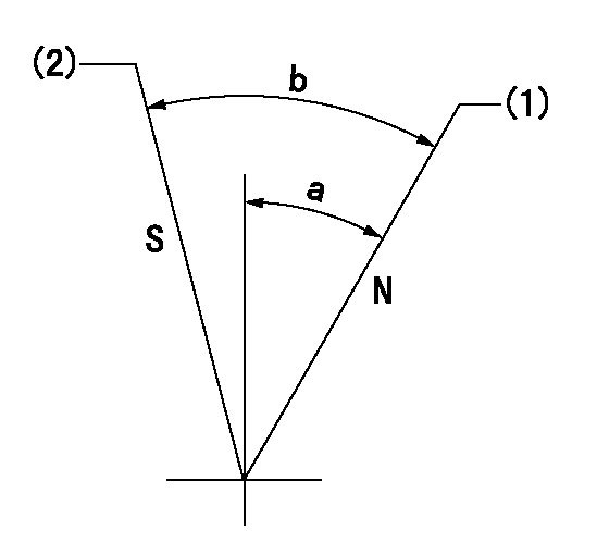
N:Pump normal
S:Stop the pump.
(1)Rack position = aa
(2)Rack position bb
----------
aa=20mm bb=1mm
----------
a=33.5deg+-5deg b=37deg+-5deg
----------
aa=20mm bb=1mm
----------
a=33.5deg+-5deg b=37deg+-5deg
0000000901

(1)Pump vertical direction
(2)Coupling's key groove position at No 1 cylinder's beginning of injection
(3)B.T.D.C.: aa
(4)Pre-stroke: bb
----------
aa=2deg bb=5.1+-0.03mm
----------
a=(2deg)
----------
aa=2deg bb=5.1+-0.03mm
----------
a=(2deg)
Stop lever angle

(1)Pointer
(2)Injection timing aligning mark
(3)Fly weight
(4)The actual shape and direction may be different from this illustration.
Operation sequence
1. Turn the prestroke actuator OFF.
2. Turn the camshaft as far as the No.1 cylinder's beginning of injection position.
3. Check that the pointer alignment mark of the injection pump and the alignment mark of the flywheel are matching.
4. If they are not matching, erase the alignment mark on the flywheel side, and stamp an alignment mark on the flywheel position that matches with the pointer side alignment mark.
5. Check again that the coupling's key groove position is in the No.1 cylinder's beginning of injection position.
----------
----------
----------
----------
0000001301

A : Stopper pin
B: Connector
----------
----------
----------
----------
0000001401

C:Shim
----------
----------
----------
----------
0000001501

A:Sealing position
B:Pre-stroke actuator
1. When installing the pre-stroke actuator on the pump, first tighten the installation bolts loosely, then move the actuator fully clockwise (viewed from the drive side).
Temporary tightening torque: 1 - 1.5 N.m (0.1 - 0.15 kgf.m)
2. Move the actuator in the counterclockwise direction when viewed from the drive side, and adjust so that it becomes the adjustment point of the adjustment value. Then tighten it.
Tightening torque: 7^9 N.m (0.7^0.9 kgf.m)
3. After prestroke actuator installation adjustment, simultaneously stamp both the actuator side and housing side.
----------
----------
----------
----------
0000001701

(Rs) rack sensor specifications
(C/U) control unit part number
(V) Rack sensor output voltage
(R) Rack position (mm)
1. Confirming governor output characteristics (rack 19 mm, span 6 mm)
(1)When the output voltages of the rack sensor are V1 and V2, check that the rack positions R1 and R2 in the table above are satisfied.
----------
----------
----------
----------
0000001901 RACK SENSOR

(VR) measurement voltage
(I) Part number of the control unit
(G) Apply red paint.
(H): End surface of the pump
1. Rack sensor adjustment (154610-0620)
(1)At governor side rack sensor output voltage V1, adjust the bobbin (A) so that the drive side rack sensor output voltage is VR+-0.01.
(2)Apply G at two places.
Connecting part between the joint (B) and the nut (F)
Connecting part between the joint (B) and the end surface of the pump (H)
----------
V1=1.6V
----------
----------
V1=1.6V
----------
Information:
(1) Crossbar (from 8B7548 Puller).(2) Spacer plate.(3) S1589 Bolt with two 1S379 Washers.(4) 1D4595 Bolt.(5) 3H465 Plate.(6) 1P2403 Dial Indicator.(7) 1P2394 Adapter Plate.(8) 1P2402 Gauge Body.Make reference to Cylinder Liner Projection in Testing and Adjusting for the complete procedure.1. Install gasket and spacer plate (2) with bolts (3) and two 1S379 Washers. Tighten bolts (3) evenly in four steps: 1st step ... 14 N m (10 lb ft)2nd step ... 35 N m (25 lb ft)3rd step ... 70 N m (50 lb ft)4th step ... 95 N m (70 lb ft)2. Install tools as shown. Tighten bolts (4) evenly in four steps: 1st step ... 7 N m (5 lb ft)2nd step ... 20 N m (15 lb ft)3rd step ... 35 N m (25 lb ft)4th step ... 70 N m (50 lb ft)3. Measure cylinder liner projection with dial indicator (6) in 1P2402 Gauge Body (8) as shown. Measure at four places around each cylinder liner near the clamped area. Cylinder liner projection measurements for any cylinder liner must be ... 0.033 to 0.175 mm (.0013 to .0069 in)Maximum permissible difference between all four measurements ... 0.05 mm (.002 in)Maximum permissible difference between average projection of any two cylinder liners next to each other ... 0.05 mm (.002 in)Maximum permissible difference between average projection of all cylinder liners under one cylinder head ... 0.10 mm (.004 in) If liner projection is not correct, turn the liner to a new position within the bore. If projection can not be corrected this way, move the liner to a different bore. If the projection can not be corrected this way, make reference to Special Instruction, Form No. FMO55228 for complete instructions on the use of 8S3140 Counterboring Tool Arrangement. 4. Minimum permissible depth to machine counterbore to adjust cylinder liner projection ... 0.76 mm (.030 in) Maximum permissible depth to machine counterbore to adjust cylinder liner projection ... 1.14 mm (.045 in)Install a 0.76 mm (.030 in) shim plus any added shims necessary to get the correct cylinder liner projection. Be sure that the 0.76 mm (.030 in) shim is directly under the cylinder liner flange.
Have questions with 107691-7010?
Group cross 107691-7010 ZEXEL
Mitsubishi
107691-7010
9 400 619 616
ME302800
INJECTION-PUMP ASSEMBLY
6D16T2
6D16T2