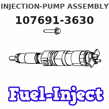
Information injection-pump assembly
BOSCH
9 400 613 283
9400613283
ZEXEL
107691-3630
1076913630
HINO
220402371A
220402371a

Rating:
Service parts 107691-3630 INJECTION-PUMP ASSEMBLY:
1.
_
7.
COUPLING PLATE
9.
_
11.
Nozzle and Holder
23600-3222B
12.
Open Pre:MPa(Kqf/cm2)
17.7{180}/21.6{220}
14.
NOZZLE
Include in #1:
107691-3630
as INJECTION-PUMP ASSEMBLY
Cross reference number
Zexel num
Bosch num
Firm num
Name
9 400 613 283
220402371A HINO
INJECTION-PUMP ASSEMBLY
J08C-UK * K 14CG TICS MD-TI6 TICS
J08C-UK * K 14CG TICS MD-TI6 TICS
Information:
1. Put the fuel injection pump housing in position on tool (A). Install race (3), bearing (2) and race (1) on the end of the camshaft in the fuel injection pump housing. 2. Put flyweights (5) in position on carrier assembly (4), and install dowels (6) to hold the flyweights in place. The flyweights must move freely on the dowels and have 0.010 to 0.230 mm (.0004 to .0090 in.) end play. 3. Install governor shaft (7) on carrier assembly (4). 4. Install dowel (8) in governor shaft (7), and slide carrier assembly (4) down on the governor shaft until dowel (8) fits into the slot in the carrier assembly.5. Install carrier assembly (4) on the end of the camshaft. 6. Install race (12), bearing (11), race (10) and ring (9) on riser (13). 7. Install riser (13) and spring (14), if equipped, on the governor shaft. 8. Install spool (18) and ring (19) on seat (17), and use tool (B) to install ring (20) to hold them in position.9. Install seat (17) on spring (16) and spring (16) on shield (15). 10. Install dashpot assembly (21) on the governor shaft. 11. Install ring (22) in the groove on the governor shaft. Install sleeve (23), spring (25), the sleeve and bearing (24) on the governor shaft. 12. Use tool (C) to hold spring (25) under compression, and install the ring in the groove on the governor shaft. 13. Put lever (32) in position on governor servo (30), and install pin (31) to hold the lever in place. Use a hammer and chisel to move the metal (stake) four places 90° apart on