Information injection-pump assembly
BOSCH
F 019 Z20 346
f019z20346
ZEXEL
107691-3462
1076913462
HINO
220402042B
220402042b
Rating:
Cross reference number
BOSCH
F 019 Z20 346
f019z20346
ZEXEL
107691-3462
1076913462
HINO
220402042B
220402042b
Zexel num
Bosch num
Firm num
Name
107691-3462
F 019 Z20 346
220402042B HINO
INJECTION-PUMP ASSEMBLY
J08C-K K
J08C-K K
Calibration Data:
Adjustment conditions
Test oil
1404 Test oil ISO4113 or {SAEJ967d}
1404 Test oil ISO4113 or {SAEJ967d}
Test oil temperature
degC
40
40
45
Nozzle and nozzle holder
105780-8330
Nozzle
105780-0130
Nozzle holder
105780-2250
Opening pressure
MPa
16.7
Opening pressure
kgf/cm2
170
Injection pipe
Outer diameter - inner diameter - length (mm) mm 6-2-600
Outer diameter - inner diameter - length (mm) mm 6-2-600
Overflow valve
134424-4120
Overflow valve opening pressure
kPa
255
221
289
Overflow valve opening pressure
kgf/cm2
2.6
2.25
2.95
Tester oil delivery pressure
kPa
255
255
255
Tester oil delivery pressure
kgf/cm2
2.6
2.6
2.6
RED4 control unit part number
407915-0
590
RED4 rack sensor specifications
mm
19
PS/ACT control unit part no.
407980-2
24*
Digi switch no.
17
Direction of rotation (viewed from drive side)
Left L
Left L
Injection timing adjustment
Direction of rotation (viewed from drive side)
Left L
Left L
Injection order
1-4-2-6-
3-5
Pre-stroke
mm
5.1
5.07
5.13
Beginning of injection position
Governor side NO.1
Governor side NO.1
Difference between angles 1
Cal 1-4 deg. 60 59.75 60.25
Cal 1-4 deg. 60 59.75 60.25
Difference between angles 2
Cyl.1-2 deg. 120 119.75 120.25
Cyl.1-2 deg. 120 119.75 120.25
Difference between angles 3
Cal 1-6 deg. 180 179.75 180.25
Cal 1-6 deg. 180 179.75 180.25
Difference between angles 4
Cal 1-3 deg. 240 239.75 240.25
Cal 1-3 deg. 240 239.75 240.25
Difference between angles 5
Cal 1-5 deg. 300 299.75 300.25
Cal 1-5 deg. 300 299.75 300.25
Injection quantity adjustment
Rack position
(10.3)
PWM
%
46.3
Pump speed
r/min
800
800
800
Average injection quantity
mm3/st.
83.5
82.5
84.5
Max. variation between cylinders
%
0
-3.5
3.5
Basic
*
PS407980-224*
V
2.25+-0.
01
PS407980-224*
mm
3.1+-0.0
5
Injection quantity adjustment_02
Rack position
(6.6)
PWM
%
25.2+-2.
8
Pump speed
r/min
315
315
315
Each cylinder's injection qty
mm3/st.
13
12
14
PS407980-224*
V
V1+0.05+
-0.01
PS407980-224*
mm
5+-0.03
Remarks
Refer to items regarding the pre-stroke actuator
Refer to items regarding the pre-stroke actuator
Governor adjustment
Pump speed
r/min
1210--
Advance angle
deg.
0
0
0
Load
2/5
Remarks
Start
Start
Governor adjustment_02
Pump speed
r/min
1160
Advance angle
deg.
0.3
Load
2/5
Governor adjustment_03
Pump speed
r/min
1360
Advance angle
deg.
3.3
3
3.6
Load
5/5
Remarks
Finish
Finish
0000001201
CU407980-224*
*
Actuator retarding type
*
Supply voltage
V
24
23.5
24.5
Ambient temperature
degC
23
18
28
Pre-stroke
mm
2
1.95
2.05
Output voltage
V
2.83
2.82
2.84
Adjustment
*
_02
CU407980-224*
*
Supply voltage
V
24
23.5
24.5
Ambient temperature
degC
23
18
28
Pre-stroke
mm
5.1
5.07
5.13
Output voltage
V
1.2
1
1.4
Confirmation
*
Remarks
Output voltage V1
Output voltage V1
_03
CU407980-224*
*
Supply voltage
V
24
23.5
24.5
Ambient temperature
degC
23
18
28
Output voltage
V
3.05
3.05
Confirmation of operating range
*
Test data Ex:
Speed control lever angle
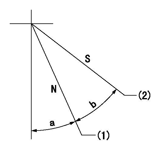
N:Pump normal
S:Stop the pump.
(1)Rack position = aa
(2)Rack position bb
----------
aa=20mm bb=1mm
----------
a=25deg+-5deg b=37deg+-5deg
----------
aa=20mm bb=1mm
----------
a=25deg+-5deg b=37deg+-5deg
0000000901

(1)Pump vertical direction
(2)Coupling's key groove position at No 1 cylinder's beginning of injection
(3)Pre-stroke: aa
(4)-
----------
aa=5.1+-0.03mm
----------
a=(20deg)
----------
aa=5.1+-0.03mm
----------
a=(20deg)
Stop lever angle

(1)Pointer
(2)Injection timing aligning mark
(3)Fly weight
(4)The actual shape and direction may be different from this illustration.
Operation sequence
1. Turn the prestroke actuator OFF.
2. Turn the camshaft as far as the No.1 cylinder's beginning of injection position.
3. Check that the pointer alignment mark of the injection pump and the alignment mark of the flywheel are matching.
4. If they are not matching, erase the alignment mark on the flywheel side, and stamp an alignment mark on the flywheel position that matches with the pointer side alignment mark.
5. Check again that the coupling's key groove position is in the No.1 cylinder's beginning of injection position.
----------
----------
----------
----------
0000001301

A : Stopper pin
B: Connector
----------
----------
----------
----------
0000001401

C:Shim
----------
----------
----------
----------
0000001501

A:Sealing position
B:Pre-stroke actuator
1. When installing the pre-stroke actuator on the pump, first tighten the installation bolts loosely, then move the actuator fully clockwise (viewed from the drive side).
Temporary tightening torque: 1 - 1.5 N.m (0.1 - 0.15 kgf.m)
2. Move the actuator in the counterclockwise direction when viewed from the drive side, and adjust so that it becomes the adjustment point of the adjustment value. Then tighten it.
Tightening torque: 7^9 N.m (0.7^0.9 kgf.m)
3. After prestroke actuator installation adjustment, simultaneously stamp both the actuator side and housing side.
----------
----------
----------
----------
0000001701

(PWM) Pulse width modulation (%)
(R) Rack position (mm)
Rack sensor output characteristics
1. Rack limit adjustment
(1)Measure the rack position R2 for PWM a2%.
(2)Confirm that it is within the range R2 = 15+-1 mm.
(3)Measure the rack position R1 at PWM a %.
(4)Confirm that it is within the range R2 - R1 = 10+-0.1 mm.
2. Check the limp home operation.
(1)Move the switch box's limp home switch to the limp home side.
(2)Confirm rack position L1 (mm ) and L2 (mm) for PWM in the above table.
3. Check the pull down operation.
(1)Confirm that the rack position is 19 mm at PWM B%.
(2)In the conditions described in the above table, move the switch box's pull down switch to the pull down side and confirm that the rack position momentarily becomes 1 mm or less.
----------
a1=16.25% a2=72.5% L1=1--mm L2=19++mm A=5 % B=95%
----------
----------
a1=16.25% a2=72.5% L1=1--mm L2=19++mm A=5 % B=95%
----------
Information:
(1) End play for shaft (new) ... 0.114 0.038 mm (.0045 .0015 in) Maximum permissible end play (worn) ... 0.20 mm (.008 in)(2) Thickness of thrust bearing (where thrust rings contact bearing) ... 5.36 0.03 mm (.211 .001 in)(3) Diameter of shaft (new) ... 15.997 to 16.005 mm (.6298 to .6301 in) Bore in the bearing (new) ... 16.035 to 16.043 mm (.6313 to .6316 in)Maximum permissible clearance between bearing and shaft (worn) ... 0.05 mm (.002 in)(4) Maximum permissible gap of oil seal ring, measured in bore of housing ... 0.25 mm (.010 in)(5) Install the compressor wheel (at room temperature) as follows: a. Put compressor wheel on the shaft.b. Put a small amount of clean engine oil on the threads.c. Tighten the nut to 14 to 17 N m (125 to 150 lb in).
Do not bend or add stress to the shaft when nut is loosened or tightened.
d. Remove nut from shaft and apply 6V1541 Quick Cure Primer on the threads of the shaft and nut followed by application of 9S3263 Retaining Compound.e. Tighten nut to 4 N m (30 lb in).f. Tighten nut more 90° rotation.(6) Thickness of each thrust ring ... 2.553 0.013 mm (.1005 .0005 in)(7) Bore in housing (new) ... 24.994 to 25.006 mm (.9840 to .9845 in) Outside diameter of the bearing (new) ... 24.882 to 24.892 mm (.9796 to .9800 in)Maximum permissible clearance between bearing and bore in housing (worn) ... 0.15 mm (.006 in)Tighten both band clamps (that hold the compressor and turbine housings to the cartridge group) with procedure that follows: a. Tighten to ... 14 1.1 N m (125 10 lb in)b. Tap (hit) clamp lightly all around.c. Tighten again to ... 14 1.1 N m (125 10 lb in)
Do not overtighten the clamps.
Torque for four nuts (put 5P3931 Anti-Seize Compound on threads) and bolts that hold turbocharger to exhaust manifold ... 55 5 N m (40 4 lb ft) Put clean engine oil in the oil inlet of the turbocharger after assembly or before installation to provide start up lubrication and/or storage protection.Turbocharger (S3B and C3B)
(1) End play for shaft (new) ... 0.102 0.025 mm (.004 .001 in) Maximum permissible end play (worn) ... 0.20 mm (.008 in)(2) Thickness of thrust bearing (where thrust rings contact bearing) ... 5.36 0.03 mm (.211 .001 in)(3) Diameter of shaft (new) ... 12.697 to 12.705 mm (.4999 to .5002 in) Bore in the bearing (new) ... 12.741 to 12.748 mm (.5016 to .5019 in)Maximum permissible clearance between bearing and shaft (worn) ... 0.05 mm (.002 in)(4) Maximum permissible gap of oil seal ring, measured in bore of housing ... 0.25 mm (.010 in)(5) Install the compressor wheel (at room temperature) as follows: a. Put compressor wheel on the shaft.b. Put a small amount of clean engine oil on the threads.c. Tighten the nut to 14 to 17 N m (125 to 150 lb
Have questions with 107691-3462?
Group cross 107691-3462 ZEXEL
Hino
Hino
107691-3462
F 019 Z20 346
220402042B
INJECTION-PUMP ASSEMBLY
J08C-K
J08C-K