Information injection-pump assembly
ZEXEL
107691-3400
1076913400
HINO
220401810A
220401810a
Rating:
Cross reference number
ZEXEL
107691-3400
1076913400
HINO
220401810A
220401810a
Zexel num
Bosch num
Firm num
Name
Calibration Data:
Adjustment conditions
Test oil
1404 Test oil ISO4113 or {SAEJ967d}
1404 Test oil ISO4113 or {SAEJ967d}
Test oil temperature
degC
40
40
45
Nozzle and nozzle holder
105780-8250
Bosch type code
1 688 901 101
Nozzle
105780-0120
Bosch type code
1 688 901 990
Nozzle holder
105780-2190
Opening pressure
MPa
20.7
Opening pressure
kgf/cm2
211
Injection pipe
Outer diameter - inner diameter - length (mm) mm 8-3-600
Outer diameter - inner diameter - length (mm) mm 8-3-600
Overflow valve
131425-0920
Overflow valve opening pressure
kPa
255
221
289
Overflow valve opening pressure
kgf/cm2
2.6
2.25
2.95
Tester oil delivery pressure
kPa
255
255
255
Tester oil delivery pressure
kgf/cm2
2.6
2.6
2.6
PS/ACT control unit part no.
407980-2
24*
Digi switch no.
17
Direction of rotation (viewed from drive side)
Left L
Left L
Injection timing adjustment
Direction of rotation (viewed from drive side)
Left L
Left L
Injection order
1-4-2-6-
3-5
Pre-stroke
mm
5.1
5.07
5.13
Beginning of injection position
Governor side NO.1
Governor side NO.1
Difference between angles 1
Cal 1-4 deg. 60 59.75 60.25
Cal 1-4 deg. 60 59.75 60.25
Difference between angles 2
Cyl.1-2 deg. 120 119.75 120.25
Cyl.1-2 deg. 120 119.75 120.25
Difference between angles 3
Cal 1-6 deg. 180 179.75 180.25
Cal 1-6 deg. 180 179.75 180.25
Difference between angles 4
Cal 1-3 deg. 240 239.75 240.25
Cal 1-3 deg. 240 239.75 240.25
Difference between angles 5
Cal 1-5 deg. 300 299.75 300.25
Cal 1-5 deg. 300 299.75 300.25
Injection quantity adjustment
Adjusting point
-
Rack position
12.1
Pump speed
r/min
750
750
750
Average injection quantity
mm3/st.
124
121
127
Max. variation between cylinders
%
0
-2
2
Basic
*
Fixing the rack
*
PS407980-224*
V
2.25+-0.
01
PS407980-224*
mm
3.1+-0.0
5
Standard for adjustment of the maximum variation between cylinders
*
Injection quantity adjustment_02
Adjusting point
Z
Rack position
6.1+-0.5
Pump speed
r/min
455
455
455
Average injection quantity
mm3/st.
8
7
9
Max. variation between cylinders
%
0
-15
15
Fixing the rack
*
PS407980-224*
V
V1+0.05+
-0.01
PS407980-224*
mm
5+-0.03
Standard for adjustment of the maximum variation between cylinders
*
Remarks
Refer to items regarding the pre-stroke actuator
Refer to items regarding the pre-stroke actuator
Injection quantity adjustment_03
Adjusting point
A
Rack position
R1(12.1)
Pump speed
r/min
750
750
750
Average injection quantity
mm3/st.
124
122
126
Basic
*
Fixing the lever
*
Boost pressure
kPa
64.7
64.7
Boost pressure
mmHg
485
485
PS407980-224*
V
2.25+-0.
01
PS407980-224*
mm
3.1+-0.0
5
Injection quantity adjustment_04
Adjusting point
B
Rack position
R1+2.8
Pump speed
r/min
1250
1250
1250
Average injection quantity
mm3/st.
140.5
134.5
146.5
Fixing the lever
*
Boost pressure
kPa
64.7
64.7
Boost pressure
mmHg
485
485
PS407980-224*
V
2.25+-0.
01
PS407980-224*
mm
3.1+-0.0
5
Injection quantity adjustment_05
Adjusting point
C
Rack position
R2-1.25
Pump speed
r/min
350
350
350
Average injection quantity
mm3/st.
86.5
80.5
92.5
Fixing the lever
*
Boost pressure
kPa
0
0
0
Boost pressure
mmHg
0
0
0
PS407980-224*
V
2.25+-0.
01
PS407980-224*
mm
3.1+-0.0
5
Boost compensator adjustment
Pump speed
r/min
350
350
350
Rack position
R2-1.25
Boost pressure
kPa
36.7
35.4
38
Boost pressure
mmHg
275
265
285
Boost compensator adjustment_02
Pump speed
r/min
350
350
350
Rack position
R2(R1-1.
65)
Boost pressure
kPa
51.3
51.3
51.3
Boost pressure
mmHg
385
385
385
Timer adjustment
Pump speed
r/min
0
Advance angle
deg.
0
0
0
Timer adjustment_02
Pump speed
r/min
-
Advance angle
deg.
0
0
0
Remarks
Measure speed (beginning of operation).
Measure speed (beginning of operation).
Timer adjustment_03
Pump speed
r/min
-
Advance angle
deg.
-1.5
-1.8
-1.2
Remarks
Measure the actual speed, stop
Measure the actual speed, stop
0000001601
CU407980-224*
*
Actuator retarding type
*
Supply voltage
V
24
23.5
24.5
Ambient temperature
degC
23
18
28
Pre-stroke
mm
2
1.95
2.05
Output voltage
V
2.83
2.82
2.84
Adjustment
*
_02
CU407980-224*
*
Supply voltage
V
24
23.5
24.5
Ambient temperature
degC
23
18
28
Pre-stroke
mm
5.1
5.07
5.13
Output voltage
V
1.2
1
1.4
Confirmation
*
Remarks
Output voltage V1
Output voltage V1
_03
CU407980-224*
*
Supply voltage
V
24
23.5
24.5
Ambient temperature
degC
23
18
28
Output voltage
V
3.05
3.05
Confirmation of operating range
*
Test data Ex:
Governor adjustment
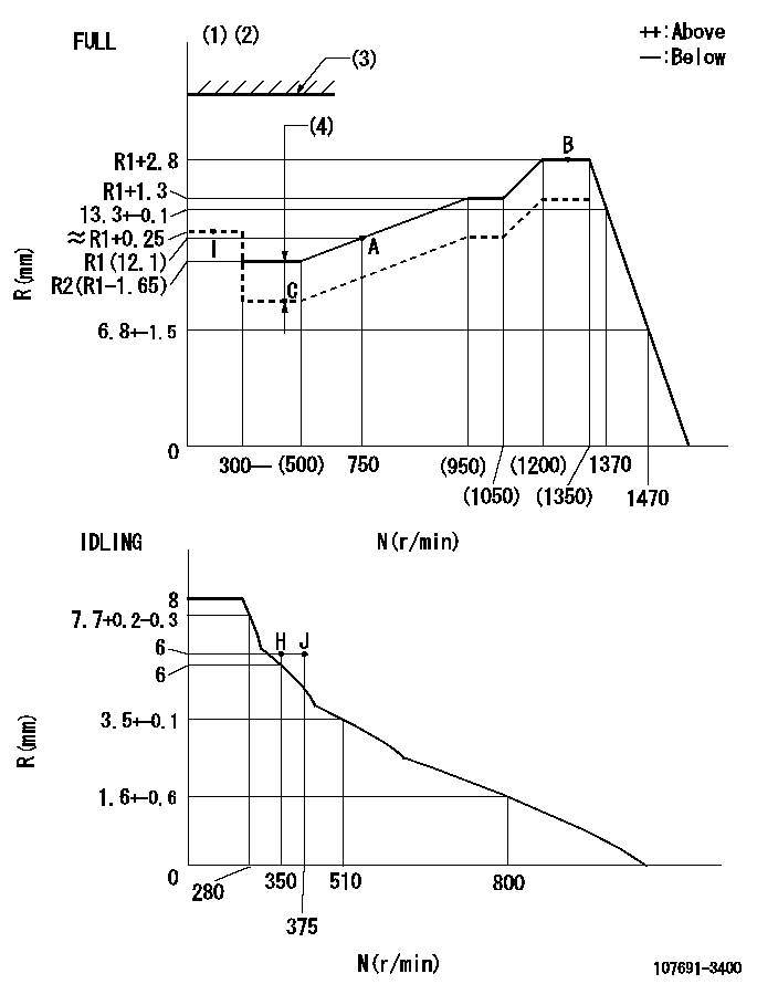
N:Pump speed
R:Rack position (mm)
(1)Torque cam stamping: T1
(2)Tolerance for racks not indicated: +-0.05mm.
(3)Stop lever's normal position setting: STL
(4)Boost compensator stroke: BCL
----------
T1=AG46 STL=(18)mm BCL=1.25+-0.1mm
----------
----------
T1=AG46 STL=(18)mm BCL=1.25+-0.1mm
----------
Speed control lever angle
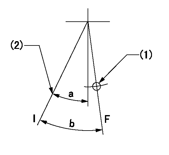
F:Full speed
I:Idle
(1)Use the hole at R = aa
(2)Stopper bolt set position 'H'
----------
aa=39.5mm
----------
a=32deg+-5deg b=42deg+-3deg
----------
aa=39.5mm
----------
a=32deg+-5deg b=42deg+-3deg
Stop lever angle
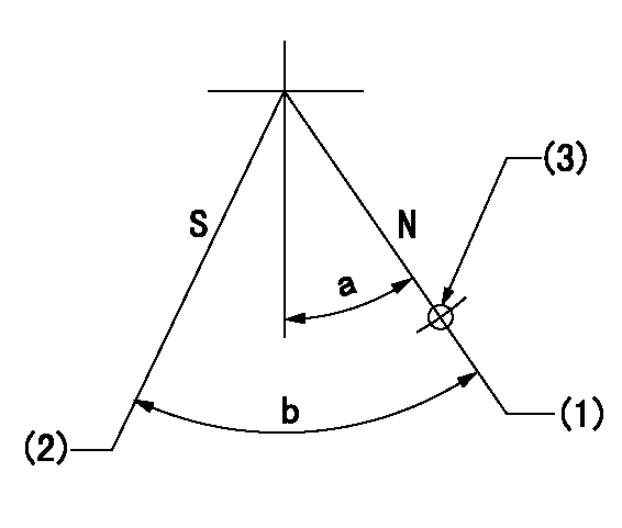
N:Pump normal
S:Stop the pump.
(1)Position at the normal side lever position (back off the stop screw and move fully to the normal side). Next, screw in the stop screw and set where it contacts the stop lever.
(2)Pump speed aa, rack position bb
(3)Use the hole above R = cc
----------
aa=0r/min bb=1.5+-0.1mm cc=28mm
----------
a=15deg+-5deg b=40deg+-5deg
----------
aa=0r/min bb=1.5+-0.1mm cc=28mm
----------
a=15deg+-5deg b=40deg+-5deg
0000001301

(1)Pump vertical direction
(2)Coupling's key groove position at No 1 cylinder's beginning of injection
(3)Pre-stroke: aa
(4)-
----------
aa=5.1+-0.03mm
----------
a=(80deg)
----------
aa=5.1+-0.03mm
----------
a=(80deg)
0000001401

(1)Pointer
(2)Injection timing aligning mark
(3)Fly weight
(4)The actual shape and direction may be different from this illustration.
Operation sequence
1. Turn the prestroke actuator OFF.
2. Turn the camshaft as far as the No.1 cylinder's beginning of injection position.
3. Check that the pointer alignment mark of the injection pump and the alignment mark of the flywheel are matching.
4. If they are not matching, erase the alignment mark on the flywheel side, and stamp an alignment mark on the flywheel position that matches with the pointer side alignment mark.
5. Check again that the coupling's key groove position is in the No.1 cylinder's beginning of injection position.
----------
----------
----------
----------
0000001701

A : Stopper pin
B: Connector
----------
----------
----------
----------
0000001801

C:Shim
----------
----------
----------
----------
0000001901

A:Sealing position
B:Pre-stroke actuator
1. When installing the pre-stroke actuator on the pump, first tighten the installation bolts loosely, then move the actuator fully clockwise (viewed from the drive side).
Temporary tightening torque: 1 - 1.5 N.m (0.1 - 0.15 kgf.m)
2. Move the actuator in the counterclockwise direction when viewed from the drive side, and adjust so that it becomes the adjustment point of the adjustment value. Then tighten it.
Tightening torque: 7^9 N.m (0.7^0.9 kgf.m)
3. After prestroke actuator installation adjustment, simultaneously stamp both the actuator side and housing side.
----------
----------
----------
----------
0000002201 RACK SENSOR

(VR) measurement voltage
(I) Part number of the control unit
(G) Apply red paint.
(H): End surface of the pump
1. Rack sensor adjustment (-0620)
(1)Fix the speed control lever at the full position
(2)Set the speed to N1 r/min.
(If the boost compensator is provided, apply boost pressure.)
(3)Adjust the bobbin (A) so that the rack sensor's output voltage is VR+-0.01.
(4)At that time, rack position must be Ra.
(5)Apply G at two places.
Connecting part between the joint (B) and the nut (F)
Connecting part between the joint (B) and the end surface of the pump (H)
----------
N1=1250r/min Ra=R1(12.1)+2.8mm
----------
----------
N1=1250r/min Ra=R1(12.1)+2.8mm
----------
0000002301 AIR CYLINDER
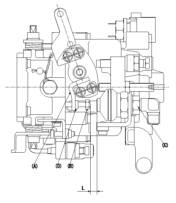
1. Air cylinder adjustment procedure
(1)Set the speed lever at idle.
(2)Temporarily set the clearance between the air cylinder (C) and the set bolt (B) to L1.
(3)Set the speed at N.
(4)Apply positive pressure P1 to the air cylinder (C).
(5)Gradually push out the set bolt (B).
(6)Tighten the nut (D) at the point where the rack position is Ra at speed N.
(7)Apply positive pressure P1 several times.
(8)Confirm that the lever returns to the idle position at positive pressure P2.
----------
L=(6)mm N=410r/min P1=392+98kPa(4+1kgf/cm2) P2=0kPa(0kgf/cm2) Ra=6+-0.1mm
----------
----------
L=(6)mm N=410r/min P1=392+98kPa(4+1kgf/cm2) P2=0kPa(0kgf/cm2) Ra=6+-0.1mm
----------
Information:
1. Remove carbon seal dam (2) with pliers. Remove compression seal (1). 2. Install a new compression seal on the nozzle. Install a new carbon seal dam with tool (B).3. Make sure the bore in the cylinder head and the fuel inlet fittings are clean.4. Install new O-ring seals on adapter (3) and fuel injection nozzle (4).5. Install the fuel injection nozzle in the head. Turn and push the nozzle into its correct position. Never put lubricant on the nozzle or bore in the cylinder head. 6. Install the adapter in the head. Connect the nozzle and fuel injection line to the adapter. Tighten the nuts to a torque of 40 7 N m (30 5 lb.ft.).7. Install the spacer and clamp (5) that hold the nozzle to the cylinder head. end by:a) install rocker shaftsDisassemble Fuel Injection Nozzles (9N3979 & 1W5829)
start by:a) remove fuel injection nozzles Do not disassemble any nozzle until test has shown it is needed. Check each nozzle with tool (A) for leakage, the pressure, at which the nozzle opens, and the shape and amount of fuel (spray pattern) that comes out of the nozzle. Do not clean or make an adjustment to any nozzle that has a large (excessive) amount of return leakage. Excessive return leakage can be an indication of nozzle failures that cannot be corrected with an adjustment or cleaning and can cause engine damage. See TESTING 9N3979 & 1W5829 FUEL INJECTION NOZZLES in TESTING AND ADJUSTING.
Keep the work area and all tools extra clean. Be careful not to cause damage to the parts while the nozzles are disassembled and assembled.
1. Remove cap (1) from the fuel injection nozzle.2. Put the nozzle in tool (B). Put tool (B) and the nozzle in a vise. Do not put any part of a nozzle directly in a vise. Loosen locknut (2) while the lift adjustment screw is held. Turn the lift adjustment screw (3) counterclockwise one turn. Hold the lift adjustment screw (3) with a 5/64" hex wrench and remove the locknut (2).
If the lift adjustment screw is not turned counterclockwise one turn, the valve can be bent or the seat for the valve can be damaged when the pressure adjustment screw is turned.
3. Loosen the locknut (4) that holds the pressure adjustment screw. Use tool (D) to hold the pressure adjustment screw. 4. While the nozzle is held in one hand, tilt the nozzle and remove the pressure adjusting screw and locknut, spring, seat and valve. 5. If the valve does not slide out of the nozzle, install tool (C) and remove valve as follows: a) Push valve into nozzle with tool (C) until valve is against bottom of nozzle.b) Push down on body of tool (C) to engage collet on valve with tool (C). c) Turn nut counterclockwise and remove valve from the nozzle body. Put the parts in solvent to loosen carbon and deposits of foreign material. The body is assembled with an epoxy material and must