Information injection-pump assembly
ZEXEL
107691-3262
1076913262
HINO
220401242A
220401242a

Rating:
Cross reference number
ZEXEL
107691-3262
1076913262
HINO
220401242A
220401242a
Zexel num
Bosch num
Firm num
Name
Calibration Data:
Adjustment conditions
Test oil
1404 Test oil ISO4113 or {SAEJ967d}
1404 Test oil ISO4113 or {SAEJ967d}
Test oil temperature
degC
40
40
45
Nozzle and nozzle holder
105780-8250
Bosch type code
1 688 901 101
Nozzle
105780-0120
Bosch type code
1 688 901 990
Nozzle holder
105780-2190
Opening pressure
MPa
20.7
Opening pressure
kgf/cm2
211
Injection pipe
Outer diameter - inner diameter - length (mm) mm 8-3-600
Outer diameter - inner diameter - length (mm) mm 8-3-600
Overflow valve
131425-0920
Overflow valve opening pressure
kPa
255
221
289
Overflow valve opening pressure
kgf/cm2
2.6
2.25
2.95
Tester oil delivery pressure
kPa
255
255
255
Tester oil delivery pressure
kgf/cm2
2.6
2.6
2.6
PS/ACT control unit part no.
407980-2
24*
Digi switch no.
17
Direction of rotation (viewed from drive side)
Left L
Left L
Injection timing adjustment
Direction of rotation (viewed from drive side)
Left L
Left L
Injection order
1-4-2-6-
3-5
Pre-stroke
mm
5.1
5.07
5.13
Beginning of injection position
Governor side NO.1
Governor side NO.1
Difference between angles 1
Cal 1-4 deg. 60 59.75 60.25
Cal 1-4 deg. 60 59.75 60.25
Difference between angles 2
Cyl.1-2 deg. 120 119.75 120.25
Cyl.1-2 deg. 120 119.75 120.25
Difference between angles 3
Cal 1-6 deg. 180 179.75 180.25
Cal 1-6 deg. 180 179.75 180.25
Difference between angles 4
Cal 1-3 deg. 240 239.75 240.25
Cal 1-3 deg. 240 239.75 240.25
Difference between angles 5
Cal 1-5 deg. 300 299.75 300.25
Cal 1-5 deg. 300 299.75 300.25
Injection quantity adjustment
Adjusting point
-
Rack position
12.4
Pump speed
r/min
750
750
750
Average injection quantity
mm3/st.
116
113
119
Max. variation between cylinders
%
0
-3.5
3.5
Basic
*
Fixing the rack
*
PS407980-224*
V
2.25+-0.
01
PS407980-224*
mm
3.1+-0.0
5
Standard for adjustment of the maximum variation between cylinders
*
Injection quantity adjustment_02
Adjusting point
Z
Rack position
8+-0.5
Pump speed
r/min
440
440
440
Each cylinder's injection qty
mm3/st.
13.5
12.5
14.5
Fixing the rack
*
PS407980-224*
V
V1+0.05+
-0.01
PS407980-224*
mm
5+-0.03
Standard for adjustment of the maximum variation between cylinders
*
Remarks
Refer to items regarding the pre-stroke actuator
Refer to items regarding the pre-stroke actuator
Injection quantity adjustment_03
Adjusting point
A
Rack position
R1(12.4)
Pump speed
r/min
750
750
750
Average injection quantity
mm3/st.
116
114
118
Basic
*
Fixing the lever
*
Boost pressure
kPa
57.3
57.3
Boost pressure
mmHg
430
430
PS407980-224*
V
2.25+-0.
01
PS407980-224*
mm
3.1+-0.0
5
Injection quantity adjustment_04
Adjusting point
B
Rack position
R1+2.15
Pump speed
r/min
1250
1250
1250
Average injection quantity
mm3/st.
129
123
135
Fixing the lever
*
Boost pressure
kPa
57.3
57.3
Boost pressure
mmHg
430
430
PS407980-224*
V
2.25+-0.
01
PS407980-224*
mm
3.1+-0.0
5
Injection quantity adjustment_05
Adjusting point
C
Rack position
(R2-0.6)
Pump speed
r/min
300
300
300
Average injection quantity
mm3/st.
91
88
94
Fixing the lever
*
Boost pressure
kPa
0
0
0
Boost pressure
mmHg
0
0
0
PS407980-224*
V
2.25+-0.
01
PS407980-224*
mm
3.1+-0.0
5
Boost compensator adjustment
Pump speed
r/min
300
300
300
Rack position
(R2-0.6)
Boost pressure
kPa
24.7
23.4
26
Boost pressure
mmHg
185
175
195
Boost compensator adjustment_02
Pump speed
r/min
300
300
300
Rack position
R2[R1-1]
Boost pressure
kPa
44
44
44
Boost pressure
mmHg
330
330
330
Timer adjustment
Pump speed
r/min
0
Advance angle
deg.
0
0
0
Timer adjustment_02
Pump speed
r/min
-
Advance angle
deg.
0
0
0
Remarks
Measure speed (beginning of operation).
Measure speed (beginning of operation).
Timer adjustment_03
Pump speed
r/min
-
Advance angle
deg.
-1.5
-1.8
-1.2
Remarks
Measure the actual speed, stop
Measure the actual speed, stop
0000001601
CU407980-224*
*
Actuator retarding type
*
Supply voltage
V
24
23.5
24.5
Ambient temperature
degC
23
18
28
Pre-stroke
mm
2
1.95
2.05
Output voltage
V
2.83
2.82
2.84
Adjustment
*
_02
CU407980-224*
*
Supply voltage
V
24
23.5
24.5
Ambient temperature
degC
23
18
28
Pre-stroke
mm
5.1
5.07
5.13
Output voltage
V
1.2
1
1.4
Confirmation
*
Remarks
Output voltage V1
Output voltage V1
_03
CU407980-224*
*
Supply voltage
V
24
23.5
24.5
Ambient temperature
degC
23
18
28
Output voltage
V
3.05
3.05
Confirmation of operating range
*
Test data Ex:
Governor adjustment
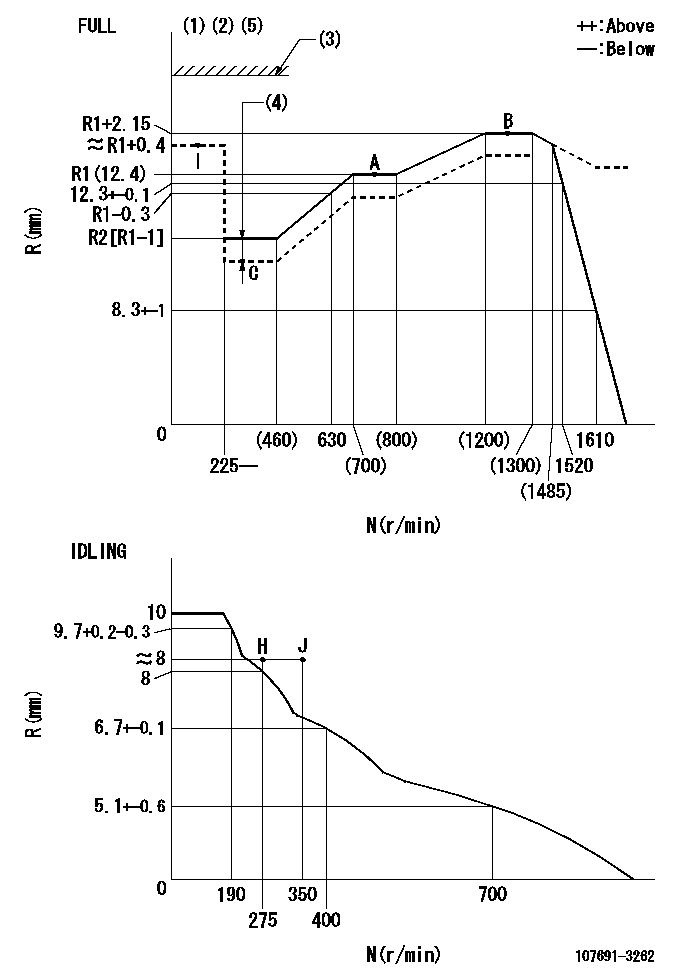
N:Pump speed
R:Rack position (mm)
(1)Torque cam stamping: T1
(2)Tolerance for racks not indicated: +-0.05mm.
(3)Stop lever's normal position setting: RA
(4)Boost compensator stroke: BCL
(5)When setting the stop lever after governor adjustment, confirm that rack position Ra (point B) can be obtained at the full setting.
----------
T1=AF50 RA=(18)mm BCL=(0.6)+-0.1mm Ra=R1(12.4)+2.15mm
----------
----------
T1=AF50 RA=(18)mm BCL=(0.6)+-0.1mm Ra=R1(12.4)+2.15mm
----------
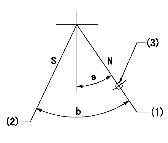
Speed control lever angle

F:Full speed
I:Idle
(1)Use the hole at R = aa
(2)Stopper bolt setting
----------
aa=50mm
----------
a=8deg+-5deg b=36.5deg+-3deg
----------
aa=50mm
----------
a=8deg+-5deg b=36.5deg+-3deg
Stop lever angle
N:Pump normal
S:Stop the pump.
(1)Rack position = aa, stopper bolt setting
(2)Speed = bb, rack position = cc
(3)Use the hole above R = dd
----------
aa=(18)mm bb=0r/min cc=1.5+-0.1mm dd=40mm
----------
a=15deg+-5deg b=35deg+-5deg
----------
aa=(18)mm bb=0r/min cc=1.5+-0.1mm dd=40mm
----------
a=15deg+-5deg b=35deg+-5deg
0000001301

(1)Pump vertical direction
(2)Coupling's key groove position at No 1 cylinder's beginning of injection
(3)Pre-stroke: aa
(4)-
----------
aa=5.1+-0.03mm
----------
a=(80deg)
----------
aa=5.1+-0.03mm
----------
a=(80deg)
0000001401

(1)Pointer
(2)Injection timing aligning mark
(3)Fly weight
(4)The actual shape and direction may be different from this illustration.
Operation sequence
1. Turn the prestroke actuator OFF.
2. Turn the camshaft as far as the No.1 cylinder's beginning of injection position.
3. Check that the pointer alignment mark of the injection pump and the alignment mark of the flywheel are matching.
4. If they are not matching, erase the alignment mark on the flywheel side, and stamp an alignment mark on the flywheel position that matches with the pointer side alignment mark.
5. Check again that the coupling's key groove position is in the No.1 cylinder's beginning of injection position.
----------
----------
----------
----------
0000001701

A : Stopper pin
B: Connector
----------
----------
----------
----------
0000001801

C:Shim
----------
----------
----------
----------
0000001901

A:Sealing position
B:Pre-stroke actuator
1. When installing the pre-stroke actuator on the pump, first tighten the installation bolts loosely, then move the actuator fully clockwise (viewed from the drive side).
Temporary tightening torque: 1 - 1.5 N.m (0.1 - 0.15 kgf.m)
2. Move the actuator in the counterclockwise direction when viewed from the drive side, and adjust so that it becomes the adjustment point of the adjustment value. Then tighten it.
Tightening torque: 7^9 N.m (0.7^0.9 kgf.m)
3. After prestroke actuator installation adjustment, simultaneously stamp both the actuator side and housing side.
----------
----------
----------
----------
0000002201 RACK SENSOR

(VR) measurement voltage
(I) Part number of the control unit
(G) Apply red paint.
(H): End surface of the pump
1. Rack sensor adjustment (-0620)
(1)Fix the speed control lever at the full position
(2)Set the speed to N1 r/min.
(If the boost compensator is provided, apply boost pressure.)
(3)Adjust the bobbin (A) so that the rack sensor's output voltage is VR+-0.01.
(4)At that time, rack position must be Ra.
(5)Apply G at two places.
Connecting part between the joint (B) and the nut (F)
Connecting part between the joint (B) and the end surface of the pump (H)
----------
N1=1250r/min Ra=R1(12.4)+2.15mm
----------
----------
N1=1250r/min Ra=R1(12.4)+2.15mm
----------
Information:
Shunt-Type Cooling System
A shunt-type cooling system for the engine is recommended. A shunt-type cooling system radiator has a normal top tank (9) above the radiator core (10) and an expansion tank (2) above (any location) the top tank.An air and coolant tube (7) allows excess air and coolant in the radiator top tank to flow into the expansion tank. The expansion tank has a shunt line (3) which connects to the water pump (11) inlet. The shunt system maintains a positive head of coolant at the pump inlet to prevent cavitation in the pump under all operating conditions.When initially filling the cooling system, the coolant in expansion tank (2) flows through shunt line (3) to the water pump inlet, flows through pump (11), and fills engine cylinder block (13) from the bottom. Coolant flowing into the bottom of the block forces the air out through the top of temperature regulator housing (4), through tube (7) into expansion tank (2).It is a good procedure, after filling the system, to immediately start the engine and make certain the cooling system is full after a few minutes of engine operation. The operating water pump circulates the coolant through the engine, to drive out any air that could have been trapped in the engine. It may be necessary to add more coolant to fill the system.
SHUNT-TYPE RADIATOR COOLING SYSTEM-SCHEMATIC (Temperature regulator partially open)
1-Radiator cap (pressure regulating valve). 2-Expansion tank. 3-Shunt line tube. 4-Temperature regulator (thermostat) housing. 5-Cylinder liners (six). 6-Cylinder head. 7-Air and coolant bleed tube (between radiator top tank and expansion tank). 8-Radiator coolant bypass tube. 9-Radiator top tank. 10-Radiator core. 11-Water pump. 12-Engine lubricating oil cooler. 13-Cylinder block.Cylinder Head
CYLINDER HEAD-END VIEW
1-Precombustion chamber (six). 2-Spring (twelve). 3-Lock (twenty four). 4-Rotocoil assembly (twelve). 5-Rocker arm (twelve). 6-Push rod (twelve). 7-Air inlet manifold (in head). 8-Valve seat insert (six inlet, six exhaust). 9-Valve (six inlet, six exhaust).This overhead valve (OHV) cylinder head has one inlet and one exhaust valve for each engine cylinder. Rocker arms (5) are operated by the camshaft, in the engine cylinder block, cam followers (lifters) and push rods (6) which open and close valves (9) at the proper time. Each rocker arm has an adjustable contact to obtain the recommended valve lash (valve clearance). Each valve spring (2), to close a valve, is retained by locks (3) and a rotocoil assembly (4). The rotocoil will rotate a valve stem approximately one third of a degree each time the valve opens and closes. This will rotate the valve about one revolution per minute when the engine is operating at full load RPM.The valve bushings (guides) and valve seat inserts (8) can be removed, if necessary, and new ones installed. The valve seats are ground at 30° angles. The high heat resistant steel inlet valves and stellite exhaust valves are gound slightly less (about one fourth of a degree) than 30° angles. The interference angles between the valves and valve seats provide for better seating for longer periods of time.The inlet