Information injection-pump assembly
ZEXEL
107691-3260
1076913260
HINO
220401240A
220401240a

Rating:
Cross reference number
ZEXEL
107691-3260
1076913260
HINO
220401240A
220401240a
Zexel num
Bosch num
Firm num
Name
Calibration Data:
Adjustment conditions
Test oil
1404 Test oil ISO4113 or {SAEJ967d}
1404 Test oil ISO4113 or {SAEJ967d}
Test oil temperature
degC
40
40
45
Nozzle and nozzle holder
105780-8250
Bosch type code
1 688 901 101
Nozzle
105780-0120
Bosch type code
1 688 901 990
Nozzle holder
105780-2190
Opening pressure
MPa
20.7
Opening pressure
kgf/cm2
211
Injection pipe
Outer diameter - inner diameter - length (mm) mm 8-3-600
Outer diameter - inner diameter - length (mm) mm 8-3-600
Overflow valve
131425-0920
Overflow valve opening pressure
kPa
255
221
289
Overflow valve opening pressure
kgf/cm2
2.6
2.25
2.95
Tester oil delivery pressure
kPa
255
255
255
Tester oil delivery pressure
kgf/cm2
2.6
2.6
2.6
PS/ACT control unit part no.
407980-2
24*
Digi switch no.
17
Direction of rotation (viewed from drive side)
Left L
Left L
Injection timing adjustment
Direction of rotation (viewed from drive side)
Left L
Left L
Injection order
1-4-2-6-
3-5
Pre-stroke
mm
5.1
5.07
5.13
Beginning of injection position
Governor side NO.1
Governor side NO.1
Difference between angles 1
Cal 1-4 deg. 60 59.75 60.25
Cal 1-4 deg. 60 59.75 60.25
Difference between angles 2
Cyl.1-2 deg. 120 119.75 120.25
Cyl.1-2 deg. 120 119.75 120.25
Difference between angles 3
Cal 1-6 deg. 180 179.75 180.25
Cal 1-6 deg. 180 179.75 180.25
Difference between angles 4
Cal 1-3 deg. 240 239.75 240.25
Cal 1-3 deg. 240 239.75 240.25
Difference between angles 5
Cal 1-5 deg. 300 299.75 300.25
Cal 1-5 deg. 300 299.75 300.25
Injection quantity adjustment
Adjusting point
-
Rack position
12.8
Pump speed
r/min
750
750
750
Average injection quantity
mm3/st.
125
122
128
Max. variation between cylinders
%
0
-2
2
Basic
*
Fixing the rack
*
PS407980-224*
V
2.25+-0.
01
PS407980-224*
mm
3.1+-0.0
5
Standard for adjustment of the maximum variation between cylinders
*
Injection quantity adjustment_02
Adjusting point
Z
Rack position
8+-0.5
Pump speed
r/min
420
420
420
Average injection quantity
mm3/st.
13.5
12.5
14.5
Max. variation between cylinders
%
0
-15
15
Fixing the rack
*
PS407980-224*
V
V1+0.05+
-0.01
PS407980-224*
mm
5+-0.03
Standard for adjustment of the maximum variation between cylinders
*
Remarks
Refer to items regarding the pre-stroke actuator
Refer to items regarding the pre-stroke actuator
Injection quantity adjustment_03
Adjusting point
A
Rack position
R1(12.8)
Pump speed
r/min
750
750
750
Average injection quantity
mm3/st.
125
123
127
Basic
*
Fixing the lever
*
Boost pressure
kPa
51.3
51.3
Boost pressure
mmHg
385
385
PS407980-224*
V
2.25+-0.
01
PS407980-224*
mm
3.1+-0.0
5
Injection quantity adjustment_04
Adjusting point
B
Rack position
R1+2.15
Pump speed
r/min
1250
1250
1250
Average injection quantity
mm3/st.
138
132
144
Fixing the lever
*
Boost pressure
kPa
51.3
51.3
Boost pressure
mmHg
385
385
PS407980-224*
V
2.25+-0.
01
PS407980-224*
mm
3.1+-0.0
5
Injection quantity adjustment_05
Adjusting point
C
Rack position
R2-0.6
Pump speed
r/min
300
300
300
Average injection quantity
mm3/st.
107
101
113
Fixing the lever
*
Boost pressure
kPa
0
0
0
Boost pressure
mmHg
0
0
0
PS407980-224*
V
2.25+-0.
01
PS407980-224*
mm
3.1+-0.0
5
Boost compensator adjustment
Pump speed
r/min
300
300
300
Rack position
R2-0.6
Boost pressure
kPa
18
16.7
19.3
Boost pressure
mmHg
135
125
145
Boost compensator adjustment_02
Pump speed
r/min
300
300
300
Rack position
R2(R1-1)
Boost pressure
kPa
38
38
38
Boost pressure
mmHg
285
285
285
Timer adjustment
Pump speed
r/min
0
Advance angle
deg.
0
0
0
Timer adjustment_02
Pump speed
r/min
-
Advance angle
deg.
0
0
0
Remarks
Measure speed (beginning of operation).
Measure speed (beginning of operation).
Timer adjustment_03
Pump speed
r/min
-
Advance angle
deg.
-1.5
-1.8
-1.2
Remarks
Measure the actual speed, stop
Measure the actual speed, stop
0000001601
CU407980-224*
*
Actuator retarding type
*
Supply voltage
V
24
23.5
24.5
Ambient temperature
degC
23
18
28
Pre-stroke
mm
2
1.95
2.05
Output voltage
V
2.83
2.82
2.84
Adjustment
*
_02
CU407980-224*
*
Supply voltage
V
24
23.5
24.5
Ambient temperature
degC
23
18
28
Pre-stroke
mm
5.1
5.07
5.13
Output voltage
V
1.2
1
1.4
Confirmation
*
Remarks
Output voltage V1
Output voltage V1
_03
CU407980-224*
*
Supply voltage
V
24
23.5
24.5
Ambient temperature
degC
23
18
28
Output voltage
V
3.05
3.05
Confirmation of operating range
*
Test data Ex:
Governor adjustment
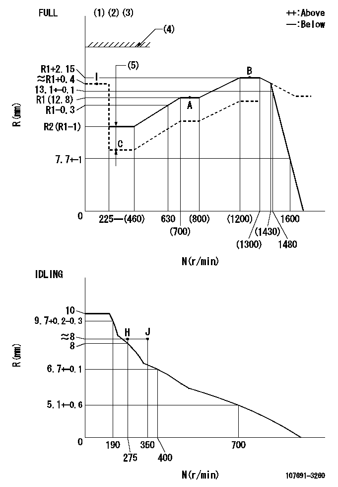
N:Pump speed
R:Rack position (mm)
(1)Torque cam stamping: T1
(2)Tolerance for racks not indicated: +-0.05mm.
(3)When setting the stop lever after governor adjustment, confirm that rack position Ra (point B) can be obtained at the full setting.
(4)Stop lever's normal position setting: RA
(5)Boost compensator stroke: BCL
----------
T1=AF50 Ra=R1+2.15mm RA=(18)mm BCL=0.6+-0.1mm
----------
----------
T1=AF50 Ra=R1+2.15mm RA=(18)mm BCL=0.6+-0.1mm
----------
Speed control lever angle

F:Full speed
I:Idle
(1)Use the hole at R = aa
(2)Stopper bolt set position 'H'
----------
aa=50mm
----------
a=8deg+-5deg b=37deg+-3deg
----------
aa=50mm
----------
a=8deg+-5deg b=37deg+-3deg
Stop lever angle
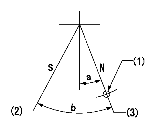
N:Pump normal
S:Stop the pump.
(1)Use the hole at R = aa
(2)Speed = bb, rack position = cc
(3)Set the stopper bolt at rack position = dd
----------
aa=40mm bb=0r/min cc=1.5+-0.1mm dd=(18)mm
----------
a=15deg+-5deg b=35deg+-5deg
----------
aa=40mm bb=0r/min cc=1.5+-0.1mm dd=(18)mm
----------
a=15deg+-5deg b=35deg+-5deg
0000001301

(1)Pump vertical direction
(2)Coupling's key groove position at No 1 cylinder's beginning of injection
(3)Pre-stroke: aa
(4)-
----------
aa=5.1+-0.03mm
----------
a=(80deg)
----------
aa=5.1+-0.03mm
----------
a=(80deg)
0000001401

(1)Pointer
(2)Injection timing aligning mark
(3)Fly weight
(4)The actual shape and direction may be different from this illustration.
Operation sequence
1. Turn the prestroke actuator OFF.
2. Turn the camshaft as far as the No.1 cylinder's beginning of injection position.
3. Check that the pointer alignment mark of the injection pump and the alignment mark of the flywheel are matching.
4. If they are not matching, erase the alignment mark on the flywheel side, and stamp an alignment mark on the flywheel position that matches with the pointer side alignment mark.
5. Check again that the coupling's key groove position is in the No.1 cylinder's beginning of injection position.
----------
----------
----------
----------
0000001701

A : Stopper pin
B: Connector
----------
----------
----------
----------
0000001801

C:Shim
----------
----------
----------
----------
0000001901

A:Sealing position
B:Pre-stroke actuator
1. When installing the pre-stroke actuator on the pump, first tighten the installation bolts loosely, then move the actuator fully clockwise (viewed from the drive side).
Temporary tightening torque: 1 - 1.5 N.m (0.1 - 0.15 kgf.m)
2. Move the actuator in the counterclockwise direction when viewed from the drive side, and adjust so that it becomes the adjustment point of the adjustment value. Then tighten it.
Tightening torque: 7^9 N.m (0.7^0.9 kgf.m)
3. After prestroke actuator installation adjustment, simultaneously stamp both the actuator side and housing side.
----------
----------
----------
----------
0000002201 RACK SENSOR

(VR) measurement voltage
(I) Part number of the control unit
(G) Apply red paint.
(H): End surface of the pump
1. Rack sensor adjustment (-0620)
(1)Fix the speed control lever at the full position
(2)Set the speed to N1 r/min.
(If the boost compensator is provided, apply boost pressure.)
(3)Adjust the bobbin (A) so that the rack sensor's output voltage is VR+-0.01.
(4)At that time, rack position must be Ra.
(5)Apply G at two places.
Connecting part between the joint (B) and the nut (F)
Connecting part between the joint (B) and the end surface of the pump (H)
----------
N1=1250r/min Ra=R1(12.8)+2.15mm
----------
----------
N1=1250r/min Ra=R1(12.8)+2.15mm
----------
Information:
Camshaft
When reconditioning an engine, check the diameter of the camshaft bearing journals and the camshaft lobe height.Camshaft bearing journals have a diameter of 2.5000 .0005 in. (63.500 0.013) and the minimum diameter worn is 2.4970 in. (63.424 mm).To measure height (B) of camshaft lobes, use the following procedures: 1. Measure base circle (C) of one exhaust and one intake lobe. Make a record of each dimension.2. Add lobe lift dimension (A) to each base circle measurement. The lobe lift dimension (A) is .3071 in. (7.800 mm) for the exhaust lobe and .3077 in. (7.816 mm) for the intake lobe.3. The minimum height of lobe (B) is .025 in. (0.64 mm) less than the dimension found in Step 2.Example of finding the height of a lobe:Base circle (C) ... 1.8200 in.(46.228 mm)Add lobe lift (A) ... .3077 in.(7.816 mm)Lobe height (B) ... 2.1277 in.(54.044 mm)Maximum wear of lobe ... .025 in.(0.64 mm)Minimum height of lobe ... 2.1027 in.(53.409 mm)
CAMSHAFT LOBE
A. Lobe lift. B. Lobe height. C. Base circle.With camshaft installed in the cylinder block, check end play. End play with new components should be .007 .003 in. (0.18 0.08 mm). The maximum permissible end play is .020 in. (0.51 mm).Camshaft Followers
Use an 8S2293 Magnet to remove the cam followers.
REMOVING CAM FOLLOWERSCam followers establish a wear pattern with the camshaft lobes. Identify and reinstall the followers in the same location from which they were removed. Dishing or circular wear pattern is allowed on the cam follower face, providing the wear face keeps a polished appearance. Replace the follower if the wear face is rough or shows signs of scuffing. A new follower can be used with an old camshaft, providing the lobe is in good condition. Put engine oil on the cam followers and the camshaft lobes before installing the cam followers. Use new cam followers with a new camshaft.Camshaft Gears
1100 and 3100 Engines With Fuel Pump Camshaft Mounted Timing Advance
1. Use a 1P2320 Puller to remove the camshaft small outer gear.
PULLING SMALL GEAR (Typical Example)2. Remove the spacer immediately behind the gear.3. Use a 1P2321 Puller to remove the camshaft large inner gear.
PULLING LARGE GEAR (Typical Example)4. To install, heat both gears to a maximum temperature of 600° F. (315° C).5. Align keyway of large gear with key in camshaft. Install large inner gear on camshaft with timing mark on gear aligned with timing mark on crankshaft gear.6. Install the spacer and small outer gear.
Do not drive gears onto camshaft. Serious damage can result to camshaft or camshaft thrust pin.
Engines With Engine Camshaft Mounted Timing Advance
1. Remove screw (1) and washer (2) from end of camshaft.
REMOVING TIMING ADVANCE RETAINING SCREW
1. Screw. 2. Washer.2. Remove timing advance unit from the camshaft.3. Install puller (A), with spacer (C) over the shaft in the camshaft and spacer (B) on spacer (C) as shown and remove the gear from the camshaft.
REMOVING GEAR (Typical Example)
A. 1P2321 Puller. B. 8S5579 Spacer. C. 9S9155 Spacer.To install the gear use the following procedure:1.