Information injection-pump assembly
ZEXEL
107691-3230
1076913230
HINO
220401060A
220401060a

Rating:
Cross reference number
ZEXEL
107691-3230
1076913230
HINO
220401060A
220401060a
Zexel num
Bosch num
Firm num
Name
Calibration Data:
Adjustment conditions
Test oil
1404 Test oil ISO4113 or {SAEJ967d}
1404 Test oil ISO4113 or {SAEJ967d}
Test oil temperature
degC
40
40
45
Nozzle and nozzle holder
105780-8250
Bosch type code
1 688 901 101
Nozzle
105780-0120
Bosch type code
1 688 901 990
Nozzle holder
105780-2190
Opening pressure
MPa
20.7
Opening pressure
kgf/cm2
211
Injection pipe
Outer diameter - inner diameter - length (mm) mm 8-3-600
Outer diameter - inner diameter - length (mm) mm 8-3-600
Overflow valve
131425-0920
Overflow valve opening pressure
kPa
255
221
289
Overflow valve opening pressure
kgf/cm2
2.6
2.25
2.95
Tester oil delivery pressure
kPa
255
255
255
Tester oil delivery pressure
kgf/cm2
2.6
2.6
2.6
PS/ACT control unit part no.
407910-3
03*
Selector switch no.
03
PS/ACT control unit part no.
407980-2
24*
Digi switch no.
16
Direction of rotation (viewed from drive side)
Left L
Left L
Injection timing adjustment
Direction of rotation (viewed from drive side)
Left L
Left L
Injection order
1-4-2-6-
3-5
Pre-stroke
mm
5.1
5.07
5.13
Beginning of injection position
Governor side NO.1
Governor side NO.1
Difference between angles 1
Cal 1-4 deg. 60 59.75 60.25
Cal 1-4 deg. 60 59.75 60.25
Difference between angles 2
Cyl.1-2 deg. 120 119.75 120.25
Cyl.1-2 deg. 120 119.75 120.25
Difference between angles 3
Cal 1-6 deg. 180 179.75 180.25
Cal 1-6 deg. 180 179.75 180.25
Difference between angles 4
Cal 1-3 deg. 240 239.75 240.25
Cal 1-3 deg. 240 239.75 240.25
Difference between angles 5
Cal 1-5 deg. 300 299.75 300.25
Cal 1-5 deg. 300 299.75 300.25
Injection quantity adjustment
Adjusting point
-
Rack position
12.6
Pump speed
r/min
750
750
750
Average injection quantity
mm3/st.
132.5
129.5
135.5
Max. variation between cylinders
%
0
-2
2
Basic
*
Fixing the rack
*
PS407980-224*
V
2.25+-0.
01
PS407980-224*
mm
3.1+-0.0
5
PS407910-303*
V
1.75+-0.
01
PS407910-303*
mm
3.1+-0.0
5
Standard for adjustment of the maximum variation between cylinders
*
Injection quantity adjustment_02
Adjusting point
Z
Rack position
6.1+-0.5
Pump speed
r/min
455
455
455
Average injection quantity
mm3/st.
8
7
9
Max. variation between cylinders
%
0
-15
15
Fixing the rack
*
PS407980-224*
V
V1+0.05+
-0.01
PS407980-224*
mm
5+-0.03
PS407910-303*
V
V1-0.05+
-0.01
PS407910-303*
mm
5+-0.03
Standard for adjustment of the maximum variation between cylinders
*
Remarks
Refer to items regarding the pre-stroke actuator
Refer to items regarding the pre-stroke actuator
Injection quantity adjustment_03
Adjusting point
A
Rack position
R1(12.6)
Pump speed
r/min
750
750
750
Average injection quantity
mm3/st.
132.5
130.5
134.5
Basic
*
Fixing the lever
*
Boost pressure
kPa
61.3
61.3
Boost pressure
mmHg
460
460
PS407980-224*
V
2.25+-0.
01
PS407980-224*
mm
3.1+-0.0
5
PS407910-303*
V
1.75+-0.
01
PS407910-303*
mm
3.1+-0.0
5
Injection quantity adjustment_04
Adjusting point
B
Rack position
R1+2.7
Pump speed
r/min
1250
1250
1250
Average injection quantity
mm3/st.
146.5
140.5
152.5
Fixing the lever
*
Boost pressure
kPa
61.3
61.3
Boost pressure
mmHg
460
460
PS407980-224*
V
2.25+-0.
01
PS407980-224*
mm
3.1+-0.0
5
PS407910-303*
V
1.75+-0.
01
PS407910-303*
mm
3.1+-0.0
5
Boost compensator adjustment
Pump speed
r/min
350
350
350
Rack position
R2-2.3
Boost pressure
kPa
26.7
25.4
28
Boost pressure
mmHg
200
190
210
Boost compensator adjustment_02
Pump speed
r/min
350
350
350
Rack position
R2(R1-1.
75)
Boost pressure
kPa
48
48
48
Boost pressure
mmHg
360
360
360
Timer adjustment
Pump speed
r/min
0
Advance angle
deg.
0
0
0
Timer adjustment_02
Pump speed
r/min
-
Advance angle
deg.
0
0
0
Remarks
Measure speed (beginning of operation).
Measure speed (beginning of operation).
Timer adjustment_03
Pump speed
r/min
-
Advance angle
deg.
-1.5
-1.8
-1.2
Remarks
Measure the actual speed, stop
Measure the actual speed, stop
0000001601
CU407980-224*
*
Actuator retarding type
*
Supply voltage
V
12
11.5
12.5
Ambient temperature
degC
23
18
28
Pre-stroke
mm
2
1.95
2.05
Output voltage
V
2.83
2.82
2.84
Adjustment
*
_02
CU407980-224*
*
Supply voltage
V
12
11.5
12.5
Ambient temperature
degC
23
18
28
Pre-stroke
mm
5.1
5.07
5.13
Output voltage
V
1.2
1
1.4
Confirmation
*
Remarks
Output voltage V1
Output voltage V1
_03
CU407980-224*
*
Supply voltage
V
12
11.5
12.5
Ambient temperature
degC
23
18
28
Output voltage
V
3.05
3.05
Confirmation of operating range
*
_04
CU407910-303*
*
Actuator retarding type
*
Supply voltage
V
12
11.5
12.5
Ambient temperature
degC
23
18
28
Pre-stroke
mm
2
1.95
2.05
Output voltage
V
1.17
1.16
1.18
Adjustment
*
_05
CU407910-303*
*
Supply voltage
V
12
11.5
12.5
Ambient temperature
degC
23
18
28
Pre-stroke
mm
5.1
5.07
5.13
Output voltage
V
2.8
2.6
3
Confirmation
*
Remarks
Output voltage V1
Output voltage V1
_06
CU407910-303*
*
Supply voltage
V
12
11.5
12.5
Ambient temperature
degC
23
18
28
Output voltage
V
0.95
Confirmation of operating range
*
Test data Ex:
Governor adjustment
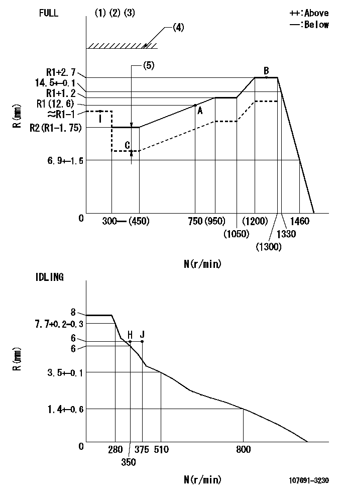
N:Pump speed
R:Rack position (mm)
(1)Torque cam stamping: T1
(2)Tolerance for racks not indicated: +-0.05mm.
(3)Set stop lever before governor adjustment. [When setting stop lever after governor adjustment, confirm that point B (Ra) can be obtained at full setting.]
(4)Stop lever's normal position setting: RA
(5)Boost compensator stroke: BCL
----------
T1=AE99 Ra=R1+2.7mm RA=(18)mm BCL=2.3+-0.1mm
----------
----------
T1=AE99 Ra=R1+2.7mm RA=(18)mm BCL=2.3+-0.1mm
----------
Speed control lever angle

F:Full speed
I:Idle
(1)Use the hole at R = aa
(2)Stopper bolt set position 'H'
----------
aa=50mm
----------
a=8deg+-5deg b=40deg+-3deg
----------
aa=50mm
----------
a=8deg+-5deg b=40deg+-3deg
Stop lever angle
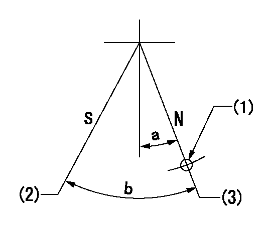
N:Pump normal
S:Stop the pump.
(1)Use the hole at R = aa
(2)Speed = bb, rack position = cc
(3)Set the stopper bolt at rack position = dd (speed = ee).
----------
aa=40mm bb=0r/min cc=1.5+-0.1mm dd=(18)mm ee=0r/min
----------
a=15deg+-5deg b=35deg+-5deg
----------
aa=40mm bb=0r/min cc=1.5+-0.1mm dd=(18)mm ee=0r/min
----------
a=15deg+-5deg b=35deg+-5deg
0000001301

(1)Pump vertical direction
(2)Coupling's key groove position at No 1 cylinder's beginning of injection
(3)Pre-stroke: aa
(4)-
----------
aa=5.1+-0.03mm
----------
a=(80deg)
----------
aa=5.1+-0.03mm
----------
a=(80deg)
0000001401

(1)Pointer
(2)Injection timing aligning mark
(3)Fly weight
(4)The actual shape and direction may be different from this illustration.
Operation sequence
1. Turn the prestroke actuator OFF.
2. Turn the camshaft as far as the No.1 cylinder's beginning of injection position.
3. Check that the pointer alignment mark of the injection pump and the alignment mark of the flywheel are matching.
4. If they are not matching, erase the alignment mark on the flywheel side, and stamp an alignment mark on the flywheel position that matches with the pointer side alignment mark.
5. Check again that the coupling's key groove position is in the No.1 cylinder's beginning of injection position.
----------
----------
----------
----------
0000001701

A : Stopper pin
B: Connector
----------
----------
----------
----------
0000001801

C:Shim
----------
----------
----------
----------
0000001901

A:Sealing position
B:Pre-stroke actuator
1. When installing the pre-stroke actuator on the pump, first tighten the installation bolts loosely, then move the actuator fully clockwise (viewed from the drive side).
Temporary tightening torque: 1 - 1.5 N.m (0.1 - 0.15 kgf.m)
2. Move the actuator in the counterclockwise direction when viewed from the drive side, and adjust so that it becomes the adjustment point of the adjustment value. Then tighten it.
Tightening torque: 7^9 N.m (0.7^0.9 kgf.m)
3. After prestroke actuator installation adjustment, simultaneously stamp both the actuator side and housing side.
----------
----------
----------
----------
0000002201 RACK SENSOR

(VR) measurement voltage
(I) Part number of the control unit
(G) Apply red paint.
(H): End surface of the pump
1. Rack sensor adjustment (-0620)
(1)Fix the speed control lever at the full position
(2)Set the speed to N1 r/min.
(If the boost compensator is provided, apply boost pressure.)
(3)Adjust the bobbin (A) so that the rack sensor's output voltage is VR+-0.01.
(4)At that time, rack position must be Ra.
(5)Apply G at two places.
Connecting part between the joint (B) and the nut (F)
Connecting part between the joint (B) and the end surface of the pump (H)
----------
N1=1250r/min Ra=R1(12.6)+2.7mm
----------
----------
N1=1250r/min Ra=R1(12.6)+2.7mm
----------
Information:
WRENCH INSTALLED
1. 8S2243 Wrench. 2. Protective cap. 3. Retaining bushing.c. Install extractor (4).d. Remove retaining bushing (3) and wrench (1).e. Remove the seal and lift fuel injection pump (5) out of the housing. Keep components together and identified as to location.4. Remove rack (7) and rack bumper spring (6).
REMOVING PUMP
4. 8S2244 Extractor. 5. Fuel injection pump.
REMOVING RACK
6. Rack bumper spring. 7. Rack.5. Use magnet (8) to remove lifters (9). Identify lifters (9) and keep them with their respective fuel injection pumps.
REMOVING LIFTERS
8. 8S2293 Magnet. 9. Lifter.6. Remove the camshaft gear assembly retaining bolt (11) and lock. Remove plate assembly (10).
REMOVING PLATE ASSEMBLY
10. Plate assembly. 11. Bolt.7. Remove camshaft gear assembly (12) from camshaft (13).
REMOVING GEAR ASSEMBLY
12. Gear assembly. 13. Camshaft.
REMOVING BOLTS
14. Lock. 15. Bolts.8. Remove bolts (15) and lock (14).9. Remove camshaft retaining plate (16).
REMOVING RETAINING PLATE
16. Retaining plate.10. Remove camshaft (13).
REMOVING CAMSHAFT
13. Camshaft.11. Use camshaft bearing removal and installation group (17) to remove the camshaft bearings from the fuel injection pump housing.
REMOVING BEARINGS
17. 8S2241 Camshaft Bearing Removal and Installation Group.Assemble Fuel Injection Pump Housing
1. Use camshaft bearing removal and installation group (17) to install the camshaft bearings in the fuel injection pump housing. The camshaft bearings must be installed with the oil holes in the bearings in line with the oil hole in the housing. The front and rear bearings must be line bored after installation. To align oil holes and line bore the bearings, See Special Instruction (GMG00672).
INSTALLING BEARINGS
17. 8S2241 Camshaft Bearing Removal and Installation Group.2. Put clean engine oil (SAE 30) on the camshaft and install camshaft (13) in the fuel injection pump housing.
INSTALLING CAMSHAFT
13. Camshaft.3. Install the camshaft retaining plate (16).4. Install lock (14) and bolts (15).
INSTALLING RETAINING PLATE
16. Retaining plate.
INSTALLING BOLTS
14. Lock. 15. Bolts.5. Install camshaft gear assembly (12) on camshaft (13).
INSTALLING GEAR ASSEMBLY
12. Gear assembly. 13. Camshaft.6. Install plate assembly (10), retaining bolt (11), and lock.
INSTALLING PLATE ASSEMBLY
10. Plate assembly. 11. Bolt. Be sure to put the spacer on bolt (11).7. Use magnet (8) to install lifters (9). The lifters (9) must be installed in the same location from which they were removed.
INSTALLING LIFTERS
8. 8S2293 Magnet. 9. Lifters.8. Lubricate the rack with clean fuel oil. Install rack (7) with timing pin slot in rack toward front of the housing. Install rack bumper spring (6) so the large diameter of the bumper spring will be against the housing. If new lifters and pumps are to be installed it will be necessary to check and/or adjust the fuel pump timing dimension. See FUEL PUMP TIMING DIMENSION SETTING-OFF ENGINE in TESTING AND ADJUSTING section of the Service Manual.
INSTALLING RACK
6. Rack bumper spring. 7. Rack.9. Remove bolts (19) and rack cover (18).
RACK COVER
18. Rack cover. 19. Bolts.
TIMING PIN INSTALLED
20. Slot in rack. 21. 8S2291 or FT887 Timing Pin.10. The rack must be centered to install the fuel injection pumps. To center the rack, pull the rack toward the governor end of the housing until centering slot (20) in the rack is under the centering pin hole.