Information injection-pump assembly
ZEXEL
107691-3180
1076913180
HINO
220401010A
220401010a

Rating:
Cross reference number
ZEXEL
107691-3180
1076913180
HINO
220401010A
220401010a
Zexel num
Bosch num
Firm num
Name
Calibration Data:
Adjustment conditions
Test oil
1404 Test oil ISO4113 or {SAEJ967d}
1404 Test oil ISO4113 or {SAEJ967d}
Test oil temperature
degC
40
40
45
Nozzle and nozzle holder
105780-8250
Bosch type code
1 688 901 101
Nozzle
105780-0120
Bosch type code
1 688 901 990
Nozzle holder
105780-2190
Opening pressure
MPa
20.7
Opening pressure
kgf/cm2
211
Injection pipe
Outer diameter - inner diameter - length (mm) mm 8-3-600
Outer diameter - inner diameter - length (mm) mm 8-3-600
Overflow valve
131425-0920
Overflow valve opening pressure
kPa
255
221
289
Overflow valve opening pressure
kgf/cm2
2.6
2.25
2.95
Tester oil delivery pressure
kPa
255
255
255
Tester oil delivery pressure
kgf/cm2
2.6
2.6
2.6
PS/ACT control unit part no.
407910-3
03*
Selector switch no.
03
PS/ACT control unit part no.
407980-2
24*
Digi switch no.
16
Direction of rotation (viewed from drive side)
Left L
Left L
Injection timing adjustment
Direction of rotation (viewed from drive side)
Left L
Left L
Injection order
1-4-2-6-
3-5
Pre-stroke
mm
5.1
5.07
5.13
Beginning of injection position
Governor side NO.1
Governor side NO.1
Difference between angles 1
Cal 1-4 deg. 60 59.75 60.25
Cal 1-4 deg. 60 59.75 60.25
Difference between angles 2
Cyl.1-2 deg. 120 119.75 120.25
Cyl.1-2 deg. 120 119.75 120.25
Difference between angles 3
Cal 1-6 deg. 180 179.75 180.25
Cal 1-6 deg. 180 179.75 180.25
Difference between angles 4
Cal 1-3 deg. 240 239.75 240.25
Cal 1-3 deg. 240 239.75 240.25
Difference between angles 5
Cal 1-5 deg. 300 299.75 300.25
Cal 1-5 deg. 300 299.75 300.25
Injection quantity adjustment
Adjusting point
-
Rack position
11.4
Pump speed
r/min
750
750
750
Average injection quantity
mm3/st.
112.5
109.5
115.5
Max. variation between cylinders
%
0
-2
2
Basic
*
Fixing the rack
*
PS407980-224*
V
2.25+-0.
01
PS407980-224*
mm
3.1+-0.0
5
PS407910-303*
V
1.75+-0.
01
PS407910-303*
mm
3.1+-0.0
5
Standard for adjustment of the maximum variation between cylinders
*
Injection quantity adjustment_02
Adjusting point
Z
Rack position
6.1+-0.5
Pump speed
r/min
455
455
455
Average injection quantity
mm3/st.
8
7
9
Max. variation between cylinders
%
0
-15
15
Fixing the rack
*
PS407980-224*
V
V1+0.05+
-0.01
PS407980-224*
mm
5+-0.03
PS407910-303*
V
V1-0.05+
-0.01
PS407910-303*
mm
5+-0.03
Standard for adjustment of the maximum variation between cylinders
*
Remarks
Refer to items regarding the pre-stroke actuator
Refer to items regarding the pre-stroke actuator
Injection quantity adjustment_03
Adjusting point
A
Rack position
R1(11.4)
Pump speed
r/min
750
750
750
Average injection quantity
mm3/st.
112.5
110.5
114.5
Basic
*
Fixing the lever
*
Boost pressure
kPa
56.7
56.7
Boost pressure
mmHg
425
425
PS407980-224*
V
2.25+-0.
01
PS407980-224*
mm
3.1+-0.0
5
PS407910-303*
V
1.75+-0.
01
PS407910-303*
mm
3.1+-0.0
5
Injection quantity adjustment_04
Adjusting point
B
Rack position
R1+1.9
Pump speed
r/min
1250
1250
1250
Average injection quantity
mm3/st.
117
111
123
Fixing the lever
*
Boost pressure
kPa
56.7
56.7
Boost pressure
mmHg
425
425
PS407980-224*
V
2.25+-0.
01
PS407980-224*
mm
3.1+-0.0
5
PS407910-303*
V
1.75+-0.
01
PS407910-303*
mm
3.1+-0.0
5
Boost compensator adjustment
Pump speed
r/min
350
350
350
Rack position
R2-1.25
Boost pressure
kPa
26.7
25.4
28
Boost pressure
mmHg
200
190
210
Boost compensator adjustment_02
Pump speed
r/min
350
350
350
Rack position
R2(R1-1.
45)
Boost pressure
kPa
43.3
43.3
43.3
Boost pressure
mmHg
325
325
325
Timer adjustment
Pump speed
r/min
0
Advance angle
deg.
0
0
0
Timer adjustment_02
Pump speed
r/min
-
Advance angle
deg.
0
0
0
Remarks
Speed, angle are actual measurements.
Speed, angle are actual measurements.
Timer adjustment_03
Pump speed
r/min
-
Advance angle
deg.
-1.5
-1.8
-1.2
Remarks
Measure the actual speed, stop
Measure the actual speed, stop
0000001601
CU407980-224*
*
Actuator retarding type
*
Supply voltage
V
12
11.5
12.5
Ambient temperature
degC
23
18
28
Pre-stroke
mm
2
1.95
2.05
Output voltage
V
2.83
2.82
2.84
Adjustment
*
_02
CU407980-224*
*
Supply voltage
V
12
11.5
12.5
Ambient temperature
degC
23
18
28
Pre-stroke
mm
5.1
5.07
5.13
Output voltage
V
1.2
1
1.4
Confirmation
*
Remarks
Output voltage V1
Output voltage V1
_03
CU407980-224*
*
Supply voltage
V
12
11.5
12.5
Ambient temperature
degC
23
18
28
Output voltage
V
3.05
3.05
Confirmation of operating range
*
_04
CU407910-303*
*
Actuator retarding type
*
Supply voltage
V
12
11.5
12.5
Ambient temperature
degC
23
18
28
Pre-stroke
mm
2
1.95
2.05
Output voltage
V
1.17
1.16
1.18
Adjustment
*
_05
CU407910-303*
*
Supply voltage
V
12
11.5
12.5
Ambient temperature
degC
23
18
28
Pre-stroke
mm
5.1
5.07
5.13
Output voltage
V
2.8
2.6
3
Confirmation
*
Remarks
Output voltage V1
Output voltage V1
_06
CU407910-303*
*
Supply voltage
V
12
11.5
12.5
Ambient temperature
degC
23
18
28
Output voltage
V
0.95
Confirmation of operating range
*
Test data Ex:
Governor adjustment
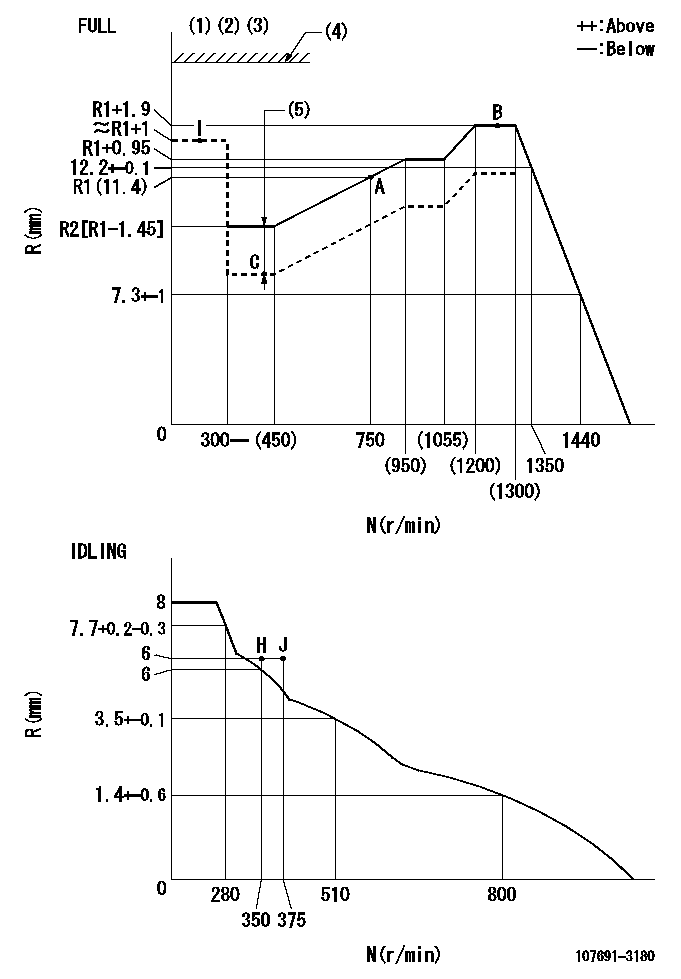
N:Pump speed
R:Rack position (mm)
(1)Torque cam stamping: T1
(2)Tolerance for racks not indicated: +-0.05mm.
(3)Set stop lever before governor adjustment. [When setting stop lever after governor adjustment, confirm that point B (Ra) can be obtained at full setting.]
(4)Stop lever's normal position setting: RA
(5)Boost compensator stroke: BCL
----------
T1=AF00 Ra=R1+1.9mm RA=(18)mm BCL=1.25+-0.1mm
----------
----------
T1=AF00 Ra=R1+1.9mm RA=(18)mm BCL=1.25+-0.1mm
----------
Speed control lever angle

F:Full speed
I:Idle
(1)Use the hole at R = aa
(2)Stopper bolt set position 'H'
----------
aa=50mm
----------
a=8deg+-5deg b=37deg+-3deg
----------
aa=50mm
----------
a=8deg+-5deg b=37deg+-3deg
Stop lever angle
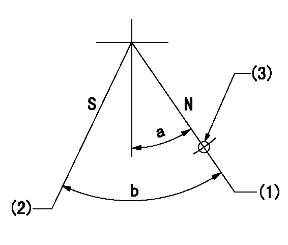
N:Pump normal
S:Stop the pump.
(1)At rack position aa, set the stopper bolt (pump speed bb r/min).
(2)Speed = cc, rack position = dd
(3)Use the hole above R = ee
----------
aa=(18)mm bb=0r/min cc=0r/min dd=1.5+-0.1mm ee=40mm
----------
a=15deg+-5deg b=35deg+-5deg
----------
aa=(18)mm bb=0r/min cc=0r/min dd=1.5+-0.1mm ee=40mm
----------
a=15deg+-5deg b=35deg+-5deg
0000001301

(1)Pump vertical direction
(2)Coupling's key groove position at No 1 cylinder's beginning of injection
(3)Pre-stroke: aa
(4)-
----------
aa=5.1+-0.03mm
----------
a=(80deg)
----------
aa=5.1+-0.03mm
----------
a=(80deg)
0000001401

(1)Pointer
(2)Injection timing aligning mark
(3)Fly weight
(4)The actual shape and direction may be different from this illustration.
Operation sequence
1. Turn the prestroke actuator OFF.
2. Turn the camshaft as far as the No.1 cylinder's beginning of injection position.
3. Check that the pointer alignment mark of the injection pump and the alignment mark of the flywheel are matching.
4. If they are not matching, erase the alignment mark on the flywheel side, and stamp an alignment mark on the flywheel position that matches with the pointer side alignment mark.
5. Check again that the coupling's key groove position is in the No.1 cylinder's beginning of injection position.
----------
----------
----------
----------
0000001701

A : Stopper pin
B: Connector
----------
----------
----------
----------
0000001801

C:Shim
----------
----------
----------
----------
0000001901

A:Sealing position
B:Pre-stroke actuator
1. When installing the pre-stroke actuator on the pump, first tighten the installation bolts loosely, then move the actuator fully clockwise (viewed from the drive side).
Temporary tightening torque: 1 - 1.5 N.m (0.1 - 0.15 kgf.m)
2. Move the actuator in the counterclockwise direction when viewed from the drive side, and adjust so that it becomes the adjustment point of the adjustment value. Then tighten it.
Tightening torque: 7^9 N.m (0.7^0.9 kgf.m)
3. After prestroke actuator installation adjustment, simultaneously stamp both the actuator side and housing side.
----------
----------
----------
----------
0000002201 LEVER
Stop lever setting
When setting the stop lever after governor adjustment, confirm that rack position Ra can be obtained at full setting.
----------
Ra=R1(11.4)+1.9mm
----------
----------
Ra=R1(11.4)+1.9mm
----------
0000002301 RACK SENSOR

(VR) measurement voltage
(I) Part number of the control unit
(G) Apply red paint.
(H): End surface of the pump
1. Rack sensor adjustment (-0620)
(1)Fix the speed control lever at the full position
(2)Set the speed to N1 r/min.
(If the boost compensator is provided, apply boost pressure.)
(3)Adjust the bobbin (A) so that the rack sensor's output voltage is VR+-0.01.
(4)At that time, rack position must be Ra.
(5)Apply G at two places.
Connecting part between the joint (B) and the nut (F)
Connecting part between the joint (B) and the end surface of the pump (H)
----------
N1=1250r/min Ra=R1(11.4)+1.9mm
----------
----------
N1=1250r/min Ra=R1(11.4)+1.9mm
----------
Information:
Pressing Parts
When one part is pressed into another, use white lead or a suitable prepared compound to lubricate the mating surfaces.Assemble tapered parts dry. Before assembling parts with tapered splines, be sure the splines are clean, dry and free from burrs. Position the parts together by hand to mesh the splines before applying pressure.Parts which are fitted together with tapered splines are always very tight. If they are not tight, inspect the tapered splines and discard the part if the splines are worn.Bolts And Bolt Torque
Use bolts of the correct length. A bolt which is too long may "bottom" before the head is tight against the part it is to hold. The threads can be damaged when a "long" bolt is removed.If a bolt is too short, there may not be enough threads engaged to hold the part securely.Apply proper torque values to all bolts and nuts when assembling Caterpillar equipment. When a specific torque value is required, the value is listed in the SPECIFICATIONS or the DISASSEMBLY AND ASSEMBLY sections of the Service Manual. Tighten all other bolts and nuts for general usage, hydraulic valve bodies, or taperlock studs to the torque values given in the charts at the front of the SPECIFICATIONS.Locks
Lockwashers, flat metal locks or cotter pins are used to lock nuts and bolts.Flat metal locks must be installed properly to be effective. Bend one end of the lock around the edge of the part. Bend the other end against one flat surface of the nut or bolt head.Always install new locks in compartments which house moving parts.When installing lockwashers on housings made of aluminum, use a flat washer between the lockwasher and the housing.
Correct and incorrect methods of installing flat metal locks.
Correct and incorrect method for lock positioning and bending.Lines And Wires
When removing or disconnecting a group of lines or wires, tag each one to assure proper assembly.Lubrication
Where applicable, fill the compartments of the components serviced with the amount, type and grade of lubricant recommended in the Lubrication and Maintenance Information part of this Manual.Rust Preventive Compound
Clean the rust preventive compound from all machined surfaces of new parts before installing them.Shims
When shims are removed, tie them together and identify them as to location. Keep shims clean and flat until they are reinstalled.Bearings
Anti-Friction Bearings
When an anti-friction bearing is removed, cover it to keep out dirt and abrasives. Wash bearings in nonflammable cleaning solution and allow them to drain dry. The bearing may be dried with compressed air but do not spin the bearing.Discard the bearings if the races and balls or rollers are pitted, scored or burned. If the bearing is serviceable, coat it with oil and wrap it in clean paper. Do not unwrap new bearings until time of installation.The life of an anti-friction bearing will be shortened if not properly lubricated. Dirt in an anti-friction bearing can cause the bearing to lock resulting in the shaft turning in the inner race or the outer race turning within the cage.
Effect of dirt in bearing.Double