Information injection-pump assembly
ZEXEL
107691-2380
1076912380

Rating:
Cross reference number
ZEXEL
107691-2380
1076912380
Zexel num
Bosch num
Firm num
Name
107691-2380
INJECTION-PUMP ASSEMBLY
Calibration Data:
Adjustment conditions
Test oil
1404 Test oil ISO4113 or {SAEJ967d}
1404 Test oil ISO4113 or {SAEJ967d}
Test oil temperature
degC
40
40
45
Nozzle and nozzle holder
105780-8250
Bosch type code
1 688 901 101
Nozzle
105780-0120
Bosch type code
1 688 901 990
Nozzle holder
105780-2190
Opening pressure
MPa
20.7
Opening pressure
kgf/cm2
211
Injection pipe
Outer diameter - inner diameter - length (mm) mm 8-3-600
Outer diameter - inner diameter - length (mm) mm 8-3-600
Overflow valve
131424-8420
Overflow valve opening pressure
kPa
255
221
289
Overflow valve opening pressure
kgf/cm2
2.6
2.25
2.95
Tester oil delivery pressure
kPa
255
255
255
Tester oil delivery pressure
kgf/cm2
2.6
2.6
2.6
PS/ACT control unit part no.
407980-2
24*
Digi switch no.
17
Direction of rotation (viewed from drive side)
Left L
Left L
Injection timing adjustment
Direction of rotation (viewed from drive side)
Left L
Left L
Injection order
1-5-3-6-
2-4
Pre-stroke
mm
5.6
5.57
5.63
Beginning of injection position
Governor side NO.1
Governor side NO.1
Difference between angles 1
Cal 1-5 deg. 60 59.75 60.25
Cal 1-5 deg. 60 59.75 60.25
Difference between angles 2
Cal 1-3 deg. 120 119.75 120.25
Cal 1-3 deg. 120 119.75 120.25
Difference between angles 3
Cal 1-6 deg. 180 179.75 180.25
Cal 1-6 deg. 180 179.75 180.25
Difference between angles 4
Cyl.1-2 deg. 240 239.75 240.25
Cyl.1-2 deg. 240 239.75 240.25
Difference between angles 5
Cal 1-4 deg. 300 299.75 300.25
Cal 1-4 deg. 300 299.75 300.25
Injection quantity adjustment
Adjusting point
-
Rack position
12.5
Pump speed
r/min
850
850
850
Average injection quantity
mm3/st.
105
103
107
Max. variation between cylinders
%
0
-3
3
Basic
*
Fixing the rack
*
PS407980-224*
V
2.25+-0.
01
PS407980-224*
mm
3.6+-0.0
5
Standard for adjustment of the maximum variation between cylinders
*
Injection quantity adjustment_02
Adjusting point
Z
Rack position
8+-0.5
Pump speed
r/min
465
465
465
Average injection quantity
mm3/st.
14
12.2
15.8
Max. variation between cylinders
%
0
-15
15
Fixing the rack
*
PS407980-224*
V
V1+0.05+
-0.01
PS407980-224*
mm
5.5+-0.0
3
Standard for adjustment of the maximum variation between cylinders
*
Remarks
Refer to items regarding the pre-stroke actuator
Refer to items regarding the pre-stroke actuator
Injection quantity adjustment_03
Adjusting point
A
Rack position
R1(12.5)
Pump speed
r/min
850
850
850
Average injection quantity
mm3/st.
105
104
106
Basic
*
Fixing the lever
*
PS407980-224*
V
2.25+-0.
01
PS407980-224*
mm
3.6+-0.0
5
Injection quantity adjustment_04
Adjusting point
B
Rack position
R1+1.45
Pump speed
r/min
1450
1450
1450
Average injection quantity
mm3/st.
102.5
98.5
106.5
Fixing the lever
*
PS407980-224*
V
2.25+-0.
01
PS407980-224*
mm
3.6+-0.0
5
Injection quantity adjustment_05
Adjusting point
C
Rack position
R1-1.3
Pump speed
r/min
450
450
450
Average injection quantity
mm3/st.
91
87
95
Fixing the lever
*
PS407980-224*
V
2.25+-0.
01
PS407980-224*
mm
3.6+-0.0
5
Timer adjustment
Pump speed
r/min
1250--
Advance angle
deg.
0
0
0
Remarks
Start
Start
Timer adjustment_02
Pump speed
r/min
1200
Advance angle
deg.
0.5
Timer adjustment_03
Pump speed
r/min
1470
Advance angle
deg.
3
2.5
3.5
Remarks
Finish
Finish
0000001601
CU407980-224*
*
Actuator retarding type
*
Supply voltage
V
24
23.5
24.5
Ambient temperature
degC
23
18
28
Pre-stroke
mm
2.5
2.45
2.55
Output voltage
V
2.83
2.82
2.84
Adjustment
*
_02
CU407980-224*
*
Supply voltage
V
24
23.5
24.5
Ambient temperature
degC
23
18
28
Pre-stroke
mm
5.6
5.57
5.63
Output voltage
V
1.2
1
1.4
Confirmation
*
Remarks
Output voltage V1
Output voltage V1
_03
CU407980-224*
*
Supply voltage
V
24
23.5
24.5
Ambient temperature
degC
23
18
28
Output voltage
V
3.05
3.05
Confirmation of operating range
*
Test data Ex:
Governor adjustment
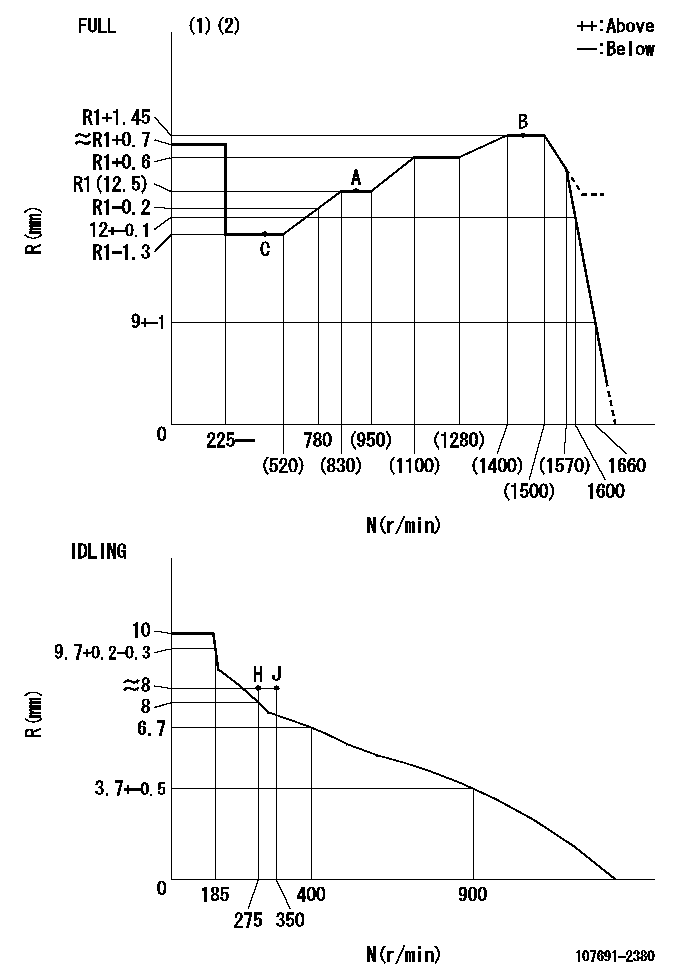
N:Pump speed
R:Rack position (mm)
(1)Torque cam stamping: T1
(2)Tolerance for racks not indicated: +-0.05mm.
----------
T1=AC90
----------
----------
T1=AC90
----------
Speed control lever angle

F:Full speed
I:Idle
(1)Accelerator lever
(2)Use the hole at R = aa
(3)Stopper bolt set position 'H'
----------
aa=38mm
----------
a=32deg+-5deg b=39.5deg+-3deg
----------
aa=38mm
----------
a=32deg+-5deg b=39.5deg+-3deg
Stop lever angle
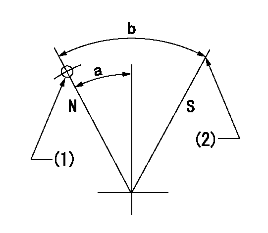
N:Pump normal
S:Stop the pump.
(1)Use the hole at R = aa
(2)Set the stopper bolt at rack position = bb, speed = cc and confirm non-injection.
----------
aa=30mm bb=1+-0.3mm cc=0r/min
----------
a=35deg+-5deg b=45deg+-5deg
----------
aa=30mm bb=1+-0.3mm cc=0r/min
----------
a=35deg+-5deg b=45deg+-5deg
0000001301
(1)Pump vertical direction
(2)Coupling's key groove position at No 1 cylinder's beginning of injection
(3)At the No 1 cylinder's beginning of injection position, stamp an aligning mark on the timer to align with the pointer's groove.
(4)Timer
(5)Pointer
(6)B.T.D.C.: aa
(7)Pre-stroke: bb
----------
aa=5deg bb=5.6+-0.03mm
----------
a=(0deg) b=(37deg)
----------
aa=5deg bb=5.6+-0.03mm
----------
a=(0deg) b=(37deg)
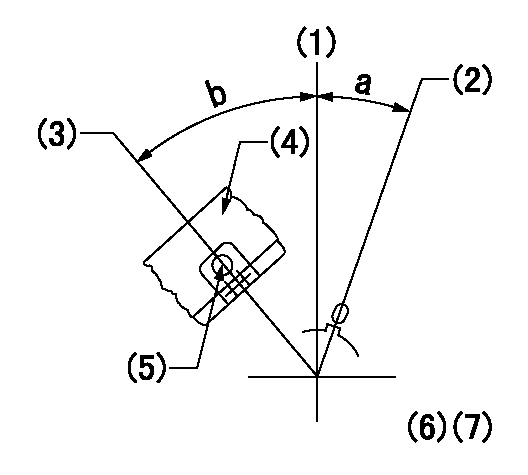
0000001401

(1)Pointer
(2)Injection timing aligning mark
(3)Fly weight
(4)The actual shape and direction may be different from this illustration.
Operation sequence
1. Turn the prestroke actuator OFF.
2. Turn the camshaft as far as the No.1 cylinder's beginning of injection position.
3. Check that the pointer alignment mark of the injection pump and the alignment mark of the flywheel are matching.
4. If they are not matching, erase the alignment mark on the flywheel side, and stamp an alignment mark on the flywheel position that matches with the pointer side alignment mark.
5. Check again that the coupling's key groove position is in the No.1 cylinder's beginning of injection position.
----------
----------
----------
----------
0000001701

A : Stopper pin
B: Connector
----------
----------
----------
----------
0000001801

C:Shim
----------
----------
----------
----------
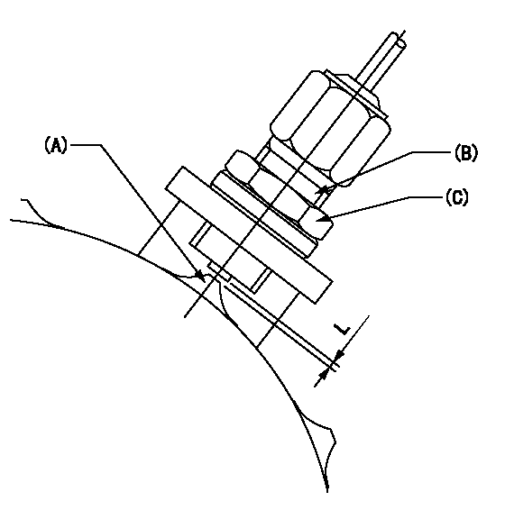
0000001901

A:Sealing position
B:Pre-stroke actuator
1. When installing the pre-stroke actuator on the pump, first tighten the installation bolts loosely, then move the actuator fully clockwise (viewed from the drive side).
Temporary tightening torque: 1 - 1.5 N.m (0.1 - 0.15 kgf.m)
2. Move the actuator in the counterclockwise direction when viewed from the drive side, and adjust so that it becomes the adjustment point of the adjustment value. Then tighten it.
Tightening torque: 7^9 N.m (0.7^0.9 kgf.m)
3. After prestroke actuator installation adjustment, simultaneously stamp both the actuator side and housing side.
----------
----------
----------
----------
0000002201 RACK SENSOR

(VR) measurement voltage
(I) Part number of the control unit
(G) Apply red paint.
(H): End surface of the pump
1. Rack sensor adjustment (-0620)
(1)Fix the speed control lever at the full position
(2)Set the speed to N1 r/min.
(If the boost compensator is provided, apply boost pressure.)
(3)Adjust the bobbin (A) so that the rack sensor's output voltage is VR+-0.01.
(4)At that time, rack position must be Ra.
(5)Apply G at two places.
Connecting part between the joint (B) and the nut (F)
Connecting part between the joint (B) and the end surface of the pump (H)
----------
N1=1450r/min Ra=R1(12.5)+1.45mm
----------
----------
N1=1450r/min Ra=R1(12.5)+1.45mm
----------
0000002301 MICRO SWITCH
Adjustment of the micro-switch
Adjust the bolt to obtain the following lever position when the micro-switch is ON.
(1)Speed N1
(2)Rack position Ra
----------
N1=275r/min Ra=8+-0.1mm
----------
----------
N1=275r/min Ra=8+-0.1mm
----------
0000002401 RACK SENSOR

V1:Supply voltage
V2f:Full side output voltage
V2i:Idle side output voltage
(A) Black
(B) Yellow
(C) Red
(D) Trimmer
(E): Shaft
(F) Nut
(G) Load lever
1. Load sensor adjustment
(1)Connect as shown in the above diagram and apply supply voltage V1.
(2)Hold the load lever (G) against the full side.
(3)Turn the shaft so that the voltage between (A) and (B) is V2.
(4)Hold the load lever (G) against the idle side.
(5)Adjust (D) so that the voltage between (A) and (B) is V2i.
(6)Repeat the above adjustments.
(7)Tighten the nut (F) at the point satisfying the standards.
(8)Hold the load lever against the full side stopper and the idle side stopper.
(9)At this time, confirm that the full side output voltage is V2f and the idle side output voltage is V2i.
----------
V1=3.57+-0.02V V2f=3+0.05V V2i=1+0.1V
----------
----------
V1=3.57+-0.02V V2f=3+0.05V V2i=1+0.1V
----------
0000002501 SPEED SENSOR
(A) Flyweight projection
(B) Pickup sensor
(c) Lock nut
Speed sensor installation
(1)Install the speed sensor so that the clearance between the sensor and the flyweight projection is L.
(This gap is the gap when the pickup sensor is returned 1 turn from where it contacts the flyweight tooth.)
----------
L=0.8~1mm
----------
----------
L=0.8~1mm
----------
Information:
This Program must be administered assoon as possible. When reporting the repair, use "PI30156" as the Partnumber and "7751" as the Group Number, "56" as the Warranty Claim DescriptionCode and "T" as the SIMS Description Code. Exception: If the repair isdone after failure, use "PI30156" as the Part Number, "7751" as the GroupNumber, "96" as the Warranty Claim Description Code, and "Z" as the SIMSDescription Code. The information supplied in this serviceletter may not be valid after the termination date of this program. Donot perform the work outlined in this Service Letter after the terminationdate without first contacting your Caterpillar product analyst. This Revised Service Letter replacesthe March 24, 2001 Service Letter. Changes were made to Parts Needed, ReworkProcedure, Service Claim Allowances, Owner Notification and Parts Disposition. This Service Letter should not be performedon engines with greater than 7500 miles (>12000 KM) or >150 hours.
COMPLETION DATE
TERMINATION DATE
September 30, 2001 March 31, 2002PROBLEM
Due to a manufacturing error, there is a possibilitythat numerous 1043568 Injector Pushrods missed the heat treating operation.Certain C-10, C-12, 3176C, and 3196 engines will need to have the injectorpushrods checked and possibly replaced. This Service letter should onlybe performed on engines with between 0 to 7500 miles (0 to 12000 kM) or0-150 hours.AFFECTED PRODUCT
Model Identification NumberTRUCK/COMMERCIAL ENGINESC-10 3CS18811 ? 193268YS7628 - 7646C-12 2KS61890 ? 632739SM277 - 3363176C IND 2AW1272 ? 13063196 IND 1DW611 ? 6143176C MAR 6BW498 ? 4993196 MAR 2XR3757 ? 38623176C Machine 3PD168 - 2023196 Machine 5ED216 - 2373176C Machine 7ZR5409 - 55163196 Machine 6AR2595 - 2635MACHINES725 AFX130-131, 142-145, 148-150,174, 177-179730 AGF217-218, 225-228345 AGS480, 562, 564, 566, 571,575, 578, 582-584ALB197APB110-112CFM27665E 6GS632, 634, 637, 639?649, 65275E 1HM310-3126HS647, 64985E 1NM230-2316JS668-669, 67295E 1SM282 ? 2896KS985, 987, 993PARTS NEEDED
AS REQUIRED
1043568 Injector Pushrods(depending on the results of the inspection,0?6 pushrods may be needed for the rework? Only individual pushrods foundto be soft need to be replaced)AS REQUIRED
Injector Group(depending on the results of the pushrodinspection , 0-6 injectors may be needed for the rework? An injector shouldbe replaced only if the pushrod for that particular injector isfound to be soft and if the engine has more than 200 MILES (322KM) or 20 HOURS.)ACTION REQUIRED
Remove the valve covers.
Using a medium to coarse flat file against thecup of the pushrod, stroke the file.
If the push rod is soft you will feel a distinctdrag as the file digs into the material.
If the push rod is hard the file will feel likeit is passing over glass as the file slides across the hard surface.
If you are not certain if a pushrod is soft orhard CALL YOUR TC OR THE CAT PRODUCT ANALYST AT:(800)447-4986.
If a pushrod is soft, remove the rocker arm andreplace the pushrod. Tighten the rocker stand bolts according to the torquevalue found in Service Manual.
IF A PUSHROD IS FOUND TO BE SOFT AND THE ENGINEHAS MORE THAN 200 miles (322 KM) OR 20 hours on it replace onlythe injector that is driven by the soft pushrod. Lubricate the two largero-ring seals with engine oil and install the injectors. Tighten the injectorhold down
Have questions with 107691-2380?
Group cross 107691-2380 ZEXEL
Mitsubishi
Mitsubishi
Mitsubishi
Mitsubishi
Mitsubishi
Mitsubishi
Mitsubishi
Mitsubishi
107691-2380
INJECTION-PUMP ASSEMBLY