Information injection-pump assembly
ZEXEL
107691-2330
1076912330
Rating:
Cross reference number
ZEXEL
107691-2330
1076912330
Zexel num
Bosch num
Firm num
Name
107691-2330
INJECTION-PUMP ASSEMBLY
Calibration Data:
Adjustment conditions
Test oil
1404 Test oil ISO4113 or {SAEJ967d}
1404 Test oil ISO4113 or {SAEJ967d}
Test oil temperature
degC
40
40
45
Nozzle and nozzle holder
105780-8250
Bosch type code
1 688 901 101
Nozzle
105780-0120
Bosch type code
1 688 901 990
Nozzle holder
105780-2190
Opening pressure
MPa
20.7
Opening pressure
kgf/cm2
211
Injection pipe
Outer diameter - inner diameter - length (mm) mm 8-3-600
Outer diameter - inner diameter - length (mm) mm 8-3-600
Overflow valve
131425-0520
Overflow valve opening pressure
kPa
255
221
289
Overflow valve opening pressure
kgf/cm2
2.6
2.25
2.95
Tester oil delivery pressure
kPa
255
255
255
Tester oil delivery pressure
kgf/cm2
2.6
2.6
2.6
PS/ACT control unit part no.
407910-3
03*
Selector switch no.
03
PS/ACT control unit part no.
407980-2
24*
Digi switch no.
16
Direction of rotation (viewed from drive side)
Left L
Left L
Injection timing adjustment
Direction of rotation (viewed from drive side)
Left L
Left L
Injection order
1-5-3-6-
2-4
Pre-stroke
mm
5.6
5.57
5.63
Beginning of injection position
Governor side NO.1
Governor side NO.1
Difference between angles 1
Cal 1-5 deg. 60 59.75 60.25
Cal 1-5 deg. 60 59.75 60.25
Difference between angles 2
Cal 1-3 deg. 120 119.75 120.25
Cal 1-3 deg. 120 119.75 120.25
Difference between angles 3
Cal 1-6 deg. 180 179.75 180.25
Cal 1-6 deg. 180 179.75 180.25
Difference between angles 4
Cyl.1-2 deg. 240 239.75 240.25
Cyl.1-2 deg. 240 239.75 240.25
Difference between angles 5
Cal 1-4 deg. 300 299.75 300.25
Cal 1-4 deg. 300 299.75 300.25
Injection quantity adjustment
Adjusting point
-
Rack position
11.3
Pump speed
r/min
800
800
800
Average injection quantity
mm3/st.
105
103.4
106.6
Max. variation between cylinders
%
0
-3
3
Basic
*
Fixing the rack
*
PS407980-224*
V
2.25+-0.
01
PS407980-224*
mm
3.6+-0.0
5
PS407910-303*
V
1.75+-0.
01
PS407910-303*
mm
3.6+-0.0
5
Standard for adjustment of the maximum variation between cylinders
*
Injection quantity adjustment_02
Adjusting point
Z
Rack position
7.5+-0.5
Pump speed
r/min
410
410
410
Average injection quantity
mm3/st.
10
8.2
11.8
Max. variation between cylinders
%
0
-15
15
Fixing the rack
*
PS407980-224*
V
V1+0.05+
-0.01
PS407980-224*
mm
5.5+-0.0
3
PS407910-303*
V
V1-0.05+
-0.01
PS407910-303*
mm
5.5+-0.0
3
Standard for adjustment of the maximum variation between cylinders
*
Remarks
Refer to items regarding the pre-stroke actuator
Refer to items regarding the pre-stroke actuator
Injection quantity adjustment_03
Adjusting point
A
Rack position
R1(11.3)
Pump speed
r/min
800
800
800
Average injection quantity
mm3/st.
105
104
106
Basic
*
Fixing the lever
*
Boost pressure
kPa
34.7
34.7
Boost pressure
mmHg
260
260
PS407980-224*
V
2.25+-0.
01
PS407980-224*
mm
3.6+-0.0
5
PS407910-303*
V
1.75+-0.
01
PS407910-303*
mm
3.6+-0.0
5
Injection quantity adjustment_04
Adjusting point
B
Rack position
R1+2.3
Pump speed
r/min
1300
1300
1300
Average injection quantity
mm3/st.
123.5
119.5
127.5
Fixing the lever
*
Boost pressure
kPa
34.7
34.7
Boost pressure
mmHg
260
260
PS407980-224*
V
2.25+-0.
01
PS407980-224*
mm
3.6+-0.0
5
PS407910-303*
V
1.75+-0.
01
PS407910-303*
mm
3.6+-0.0
5
Boost compensator adjustment
Pump speed
r/min
300
300
300
Rack position
R2-0.9
Boost pressure
kPa
6.7
5.4
8
Boost pressure
mmHg
50
40
60
Boost compensator adjustment_02
Pump speed
r/min
300
300
300
Rack position
R2(R1-0.
85)
Boost pressure
kPa
21.3
21.3
21.3
Boost pressure
mmHg
160
160
160
Timer adjustment
Pump speed
r/min
1050--
Advance angle
deg.
0
0
0
Remarks
Start
Start
Timer adjustment_02
Pump speed
r/min
1000
Advance angle
deg.
0
-0.5
0
Timer adjustment_03
Pump speed
r/min
1075
Advance angle
deg.
-1.5
-2
-1
Remarks
Finish
Finish
0000001601
CU407980-224*
*
Actuator retarding type
*
Supply voltage
V
12
11.5
12.5
Ambient temperature
degC
23
18
28
Pre-stroke
mm
2.5
2.45
2.55
Output voltage
V
2.83
2.82
2.84
Adjustment
*
_02
CU407980-224*
*
Supply voltage
V
12
11.5
12.5
Ambient temperature
degC
23
18
28
Pre-stroke
mm
5.6
5.57
5.63
Output voltage
V
1.2
1
1.4
Confirmation
*
Remarks
Output voltage V1
Output voltage V1
_03
CU407980-224*
*
Supply voltage
V
12
11.5
12.5
Ambient temperature
degC
23
18
28
Output voltage
V
3.05
3.05
Confirmation of operating range
*
_04
CU407910-303*
*
Actuator retarding type
*
Supply voltage
V
12
11.5
12.5
Ambient temperature
degC
23
18
28
Pre-stroke
mm
2.5
2.45
2.55
Output voltage
V
1.17
1.16
1.18
Adjustment
*
_05
CU407910-303*
*
Supply voltage
V
12
11.5
12.5
Ambient temperature
degC
23
18
28
Pre-stroke
mm
5.6
5.57
5.63
Output voltage
V
2.8
2.6
3
Confirmation
*
Remarks
Output voltage V1
Output voltage V1
_06
CU407910-303*
*
Supply voltage
V
12
11.5
12.5
Ambient temperature
degC
23
18
28
Output voltage
V
0.95
Confirmation of operating range
*
Test data Ex:
Governor adjustment
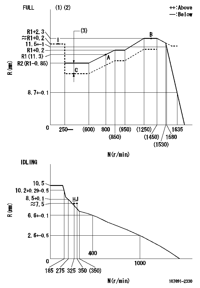
N:Pump speed
R:Rack position (mm)
(1)Torque cam stamping: T1
(2)Tolerance for racks not indicated: +-0.05mm.
(3)Boost compensator stroke: BCL
----------
T1=AC64 BCL=0.9+-0.1mm
----------
----------
T1=AC64 BCL=0.9+-0.1mm
----------
Speed control lever angle

F:Full speed
I:Idle
(1)Use the hole at R = aa
(2)Stopper bolt set position 'H'
----------
aa=40mm
----------
a=39deg+-5deg b=39.5deg+-3deg
----------
aa=40mm
----------
a=39deg+-5deg b=39.5deg+-3deg
Stop lever angle
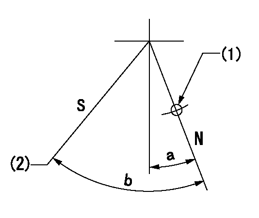
N:Pump normal
S:Stop the pump.
(1)Use the hole at R = aa
(2)Set the stopper bolt so that speed = bb and rack position = cc. (Confirm non-injection.)
----------
aa=40mm bb=1300r/min cc=1.5+-0.3mm
----------
a=6deg+-5deg b=45deg+-5deg
----------
aa=40mm bb=1300r/min cc=1.5+-0.3mm
----------
a=6deg+-5deg b=45deg+-5deg
0000001301

(1)Pump vertical direction
(2)Coupling's key groove position at No 1 cylinder's beginning of injection
(3)B.T.D.C.: aa
(4)Pre-stroke: bb
----------
aa=8deg bb=5.6+-0.03mm
----------
a=(4deg)
----------
aa=8deg bb=5.6+-0.03mm
----------
a=(4deg)
0000001401

(1)Pointer
(2)Injection timing aligning mark
(3)Fly weight
(4)The actual shape and direction may be different from this illustration.
Operation sequence
1. Turn the prestroke actuator OFF.
2. Turn the camshaft as far as the No.1 cylinder's beginning of injection position.
3. Check that the pointer alignment mark of the injection pump and the alignment mark of the flywheel are matching.
4. If they are not matching, erase the alignment mark on the flywheel side, and stamp an alignment mark on the flywheel position that matches with the pointer side alignment mark.
5. Check again that the coupling's key groove position is in the No.1 cylinder's beginning of injection position.
----------
----------
----------
----------
0000001701

A : Stopper pin
B: Connector
----------
----------
----------
----------
0000001801

C:Shim
----------
----------
----------
----------
0000001901

A:Sealing position
B:Pre-stroke actuator
1. When installing the pre-stroke actuator on the pump, first tighten the installation bolts loosely, then move the actuator fully clockwise (viewed from the drive side).
Temporary tightening torque: 1 - 1.5 N.m (0.1 - 0.15 kgf.m)
2. Move the actuator in the counterclockwise direction when viewed from the drive side, and adjust so that it becomes the adjustment point of the adjustment value. Then tighten it.
Tightening torque: 7^9 N.m (0.7^0.9 kgf.m)
3. After prestroke actuator installation adjustment, simultaneously stamp both the actuator side and housing side.
----------
----------
----------
----------
0000002201 RACK SENSOR

(VR) measurement voltage
(I) Part number of the control unit
(G) Apply red paint.
(H): End surface of the pump
1. Rack sensor adjustment (-0620)
(1)Fix the speed control lever at the full position
(2)Set the speed to N1 r/min.
(If the boost compensator is provided, apply boost pressure.)
(3)Adjust the bobbin (A) so that the rack sensor's output voltage is VR+-0.01.
(4)At that time, rack position must be Ra.
(5)Apply G at two places.
Connecting part between the joint (B) and the nut (F)
Connecting part between the joint (B) and the end surface of the pump (H)
----------
N1=1300r/min Ra=R1(11.3)+2.3mm
----------
----------
N1=1300r/min Ra=R1(11.3)+2.3mm
----------
0000002301 SPEED SENSOR
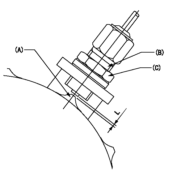
(A) Flyweight projection
(B) Pickup sensor
(c) Lock nut
Speed sensor installation
(1)Install the speed sensor so that the clearance between the sensor and the flyweight projection is L.
(This gap is the gap when the pickup sensor is returned 1 turn from where it contacts the flyweight tooth.)
----------
L=0.8~1mm
----------
----------
L=0.8~1mm
----------
Information:
The information supplied in this service letter may not be valid after the termination date of this program. Do not perform the work outlined in this Service Letter after the termination date without first contacting your Caterpillar product analyst.
This Program can only be administered after a failure occurs (any time the cylinder head has been removed).The decision whether to apply the Program is made by the dealer.When reporting the repair, use "PS5237" as the Part Number and "7755" as the Group Number.Use "96" as the WarrantyClaim Description Code and use "Z" as the SIMS Description Code.
Termination Date
January 31, 1998Problem
The 1159393 Unit Injector Lifter Assembly on some C-10 and C-12 Truck Engines may crack.
Affected Product
Model & Identification Number
C-10 (2PN1125-1979)
C-12 (1YN1294-2426)
Parts Needed
6 - 1159393 Unit Injector Lifter AssembliesAction Required
Some of the rollers may contain a material flaw on the roller surface. The flaw may appear as a faint line or scratch running parallel to the brass roller pin. Refer to Illustration 1.
1. Remove lifter bracket assemblies as outlined in the Disassembly and Assembly Manual, SENR1002-01.2. Replace all six 1159393 Unit Injector Lifter Assemblies.3. Install lifter bracket assemblies and tighten bolts to a torque of 30 N m (25 lb ft).
Illustration 1Service Claim Allowances
Labor Breakdown By Cab Type These codes and times are based on performing this repair with the cylinder head already removed.
Parts Disposition
Handle the parts in accordance with your Warranty Bulletin on warranty parts handling.
Have questions with 107691-2330?
Group cross 107691-2330 ZEXEL
107691-2330
INJECTION-PUMP ASSEMBLY