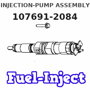
Information injection-pump assembly
ZEXEL
107691-2084
1076912084
Rating:
Cross reference number
ZEXEL
107691-2084
1076912084
Zexel num
Bosch num
Firm num
Name
107691-2084
INJECTION-PUMP ASSEMBLY
Calibration Data:
Adjustment conditions
Test oil
1404 Test oil ISO4113 or {SAEJ967d}
1404 Test oil ISO4113 or {SAEJ967d}
Test oil temperature
degC
40
40
45
Nozzle and nozzle holder
105780-8250
Bosch type code
1 688 901 101
Nozzle
105780-0120
Bosch type code
1 688 901 990
Nozzle holder
105780-2190
Opening pressure
MPa
20.7
Opening pressure
kgf/cm2
211
Injection pipe
Outer diameter - inner diameter - length (mm) mm 8-3-600
Outer diameter - inner diameter - length (mm) mm 8-3-600
Overflow valve
131425-0520
Overflow valve opening pressure
kPa
255
221
289
Overflow valve opening pressure
kgf/cm2
2.6
2.25
2.95
Tester oil delivery pressure
kPa
255
255
255
Tester oil delivery pressure
kgf/cm2
2.6
2.6
2.6
PS/ACT control unit part no.
407910-3
03*
Selector switch no.
03
PS/ACT control unit part no.
407980-2
24*
Digi switch no.
16
Direction of rotation (viewed from drive side)
Left L
Left L
Injection timing adjustment
Direction of rotation (viewed from drive side)
Left L
Left L
Injection order
1-5-3-6-
2-4
Pre-stroke
mm
5.6
5.57
5.63
Beginning of injection position
Governor side NO.1
Governor side NO.1
Difference between angles 1
Cal 1-5 deg. 60 59.75 60.25
Cal 1-5 deg. 60 59.75 60.25
Difference between angles 2
Cal 1-3 deg. 120 119.75 120.25
Cal 1-3 deg. 120 119.75 120.25
Difference between angles 3
Cal 1-6 deg. 180 179.75 180.25
Cal 1-6 deg. 180 179.75 180.25
Difference between angles 4
Cyl.1-2 deg. 240 239.75 240.25
Cyl.1-2 deg. 240 239.75 240.25
Difference between angles 5
Cal 1-4 deg. 300 299.75 300.25
Cal 1-4 deg. 300 299.75 300.25
Injection quantity adjustment
Adjusting point
-
Rack position
11.9
Pump speed
r/min
800
800
800
Average injection quantity
mm3/st.
115
113.4
116.6
Max. variation between cylinders
%
0
-3
3
Basic
*
Fixing the rack
*
PS407980-224*
V
2.25+-0.
01
PS407980-224*
mm
3.6+-0.0
5
PS407910-303*
V
1.75+-0.
01
PS407910-303*
mm
3.6+-0.0
5
Standard for adjustment of the maximum variation between cylinders
*
Injection quantity adjustment_02
Adjusting point
Z
Rack position
7.5+-0.5
Pump speed
r/min
420
420
420
Average injection quantity
mm3/st.
10
8.2
11.8
Max. variation between cylinders
%
0
-15
15
Fixing the rack
*
PS407980-224*
V
V1+0.05+
-0.01
PS407980-224*
mm
5.5+-0.0
3
PS407910-303*
V
V1-0.05+
-0.01
PS407910-303*
mm
5.5+-0.0
3
Standard for adjustment of the maximum variation between cylinders
*
Remarks
Refer to items regarding the pre-stroke actuator
Refer to items regarding the pre-stroke actuator
Injection quantity adjustment_03
Adjusting point
A
Rack position
R1(11.9)
Pump speed
r/min
800
800
800
Average injection quantity
mm3/st.
115
114
116
Basic
*
Fixing the lever
*
Boost pressure
kPa
29.3
29.3
Boost pressure
mmHg
220
220
PS407980-224*
V
2.25+-0.
01
PS407980-224*
mm
3.6+-0.0
5
PS407910-303*
V
1.75+-0.
01
PS407910-303*
mm
3.6+-0.0
5
Injection quantity adjustment_04
Adjusting point
B
Rack position
R1+2.1
Pump speed
r/min
1350
1350
1350
Average injection quantity
mm3/st.
128.5
124.5
132.5
Fixing the lever
*
Boost pressure
kPa
29.3
29.3
Boost pressure
mmHg
220
220
PS407980-224*
V
2.25+-0.
01
PS407980-224*
mm
3.6+-0.0
5
PS407910-303*
V
1.75+-0.
01
PS407910-303*
mm
3.6+-0.0
5
Injection quantity adjustment_05
Adjusting point
C
Rack position
R2(R1-1.
45)
Pump speed
r/min
500
500
500
Average injection quantity
mm3/st.
94.5
90.5
98.5
Fixing the lever
*
Boost pressure
kPa
29.3
29.3
Boost pressure
mmHg
220
220
PS407980-224*
V
2.25+-0.
01
PS407980-224*
mm
3.6+-0.0
5
PS407910-303*
V
1.75+-0.
01
PS407910-303*
mm
3.6+-0.0
5
Injection quantity adjustment_06
Adjusting point
D
Rack position
R2-0.55
Pump speed
r/min
300
300
300
Average injection quantity
mm3/st.
64.5
60.5
68.5
Fixing the lever
*
Boost pressure
kPa
0
0
0
Boost pressure
mmHg
0
0
0
PS407980-224*
V
2.25+-0.
01
PS407980-224*
mm
3.6+-0.0
5
PS407910-303*
V
1.75+-0.
01
PS407910-303*
mm
3.6+-0.0
5
Boost compensator adjustment
Pump speed
r/min
300
300
300
Rack position
R2-0.55
Boost pressure
kPa
6.7
5.4
8
Boost pressure
mmHg
50
40
60
Boost compensator adjustment_02
Pump speed
r/min
300
300
300
Rack position
R2(R1-1.
45)
Boost pressure
kPa
16
16
16
Boost pressure
mmHg
120
120
120
Timer adjustment
Pump speed
r/min
1050--
Advance angle
deg.
0
0
0
Remarks
Start
Start
Timer adjustment_02
Pump speed
r/min
1000
Advance angle
deg.
0
-0.5
0
Timer adjustment_03
Pump speed
r/min
1075
Advance angle
deg.
-1.5
-2
-1
Remarks
Finish
Finish
0000001601
CU407980-224*
*
Actuator retarding type
*
Supply voltage
V
12
11.5
12.5
Ambient temperature
degC
23
18
28
Pre-stroke
mm
2.5
2.45
2.55
Output voltage
V
2.83
2.82
2.84
Adjustment
*
_02
CU407980-224*
*
Supply voltage
V
12
11.5
12.5
Ambient temperature
degC
23
18
28
Pre-stroke
mm
5.6
5.57
5.63
Output voltage
V
1.2
1
1.4
Confirmation
*
Remarks
Output voltage V1
Output voltage V1
_03
CU407980-224*
*
Supply voltage
V
12
11.5
12.5
Ambient temperature
degC
23
18
28
Output voltage
V
3.05
3.05
Confirmation of operating range
*
_04
CU407910-303*
*
Actuator retarding type
*
Supply voltage
V
12
11.5
12.5
Ambient temperature
degC
23
18
28
Pre-stroke
mm
2.5
2.45
2.55
Output voltage
V
1.17
1.16
1.18
Adjustment
*
_05
CU407910-303*
*
Supply voltage
V
12
11.5
12.5
Ambient temperature
degC
23
18
28
Pre-stroke
mm
5.6
5.57
5.63
Output voltage
V
2.8
2.6
3
Confirmation
*
Remarks
Output voltage V1
Output voltage V1
_06
CU407910-303*
*
Supply voltage
V
12
11.5
12.5
Ambient temperature
degC
23
18
28
Output voltage
V
0.95
Confirmation of operating range
*
Test data Ex:
Governor adjustment
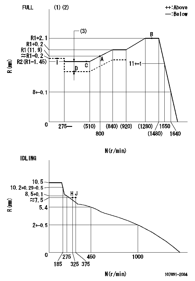
N:Pump speed
R:Rack position (mm)
(1)Torque cam stamping: T1
(2)Tolerance for racks not indicated: +-0.05mm.
(3)Boost compensator stroke: BCL
----------
T1=AB72 BCL=0.55+-0.1mm
----------
----------
T1=AB72 BCL=0.55+-0.1mm
----------
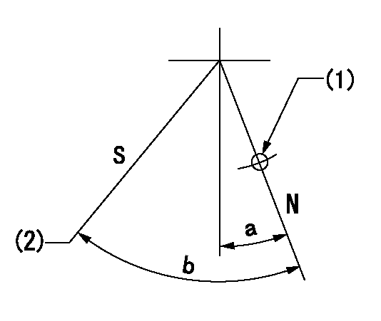
Speed control lever angle

F:Full speed
I:Idle
(1)Use the hole at R = aa
(2)Stopper bolt set position 'H'
----------
aa=40mm
----------
a=39deg+-5deg b=(39deg)+-3deg
----------
aa=40mm
----------
a=39deg+-5deg b=(39deg)+-3deg
Stop lever angle
N:Pump normal
S:Stop the pump.
(1)Use the hole at R = aa
(2)Set the stopper bolt so that speed = bb and rack position = cc. (Confirm non-injection.)
----------
aa=40mm bb=1300r/min cc=1.5+-0.3mm
----------
a=6deg+-5deg b=45deg+-5deg
----------
aa=40mm bb=1300r/min cc=1.5+-0.3mm
----------
a=6deg+-5deg b=45deg+-5deg
0000001301

(1)Pump vertical direction
(2)Coupling's key groove position at No 1 cylinder's beginning of injection
(3)B.T.D.C.: aa
(4)Pre-stroke: bb
----------
aa=8deg bb=5.6+-0.03mm
----------
a=(3deg)
----------
aa=8deg bb=5.6+-0.03mm
----------
a=(3deg)
0000001401

(1)Pointer
(2)Injection timing aligning mark
(3)Fly weight
(4)The actual shape and direction may be different from this illustration.
Operation sequence
1. Turn the prestroke actuator OFF.
2. Turn the camshaft as far as the No.1 cylinder's beginning of injection position.
3. Check that the pointer alignment mark of the injection pump and the alignment mark of the flywheel are matching.
4. If they are not matching, erase the alignment mark on the flywheel side, and stamp an alignment mark on the flywheel position that matches with the pointer side alignment mark.
5. Check again that the coupling's key groove position is in the No.1 cylinder's beginning of injection position.
----------
----------
----------
----------
0000001701

A : Stopper pin
B: Connector
----------
----------
----------
----------
0000001801

C:Shim
----------
----------
----------
----------
0000001901

A:Sealing position
B:Pre-stroke actuator
1. When installing the pre-stroke actuator on the pump, first tighten the installation bolts loosely, then move the actuator fully clockwise (viewed from the drive side).
Temporary tightening torque: 1 - 1.5 N.m (0.1 - 0.15 kgf.m)
2. Move the actuator in the counterclockwise direction when viewed from the drive side, and adjust so that it becomes the adjustment point of the adjustment value. Then tighten it.
Tightening torque: 7^9 N.m (0.7^0.9 kgf.m)
3. After prestroke actuator installation adjustment, simultaneously stamp both the actuator side and housing side.
----------
----------
----------
----------
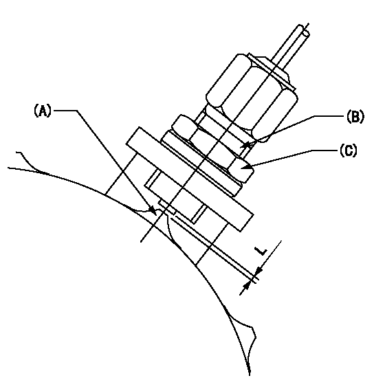
0000002201 RACK SENSOR

(VR) measurement voltage
(I) Part number of the control unit
(G) Apply red paint.
(H): End surface of the pump
1. Rack sensor adjustment (-0620)
(1)Fix the speed control lever at the full position
(2)Set the speed to N1 r/min.
(If the boost compensator is provided, apply boost pressure.)
(3)Adjust the bobbin (A) so that the rack sensor's output voltage is VR+-0.01.
(4)At that time, rack position must be Ra.
(5)Apply G at two places.
Connecting part between the joint (B) and the nut (F)
Connecting part between the joint (B) and the end surface of the pump (H)
----------
N1=1350r/min Ra=R1(11.9)+2.1mm
----------
----------
N1=1350r/min Ra=R1(11.9)+2.1mm
----------
0000002301 SPEED SENSOR
(A) Flyweight projection
(B) Pickup sensor
(c) Lock nut
Speed sensor installation
(1)Install the speed sensor so that the clearance between the sensor and the flyweight projection is L.
(This gap is the gap when the pickup sensor is returned 1 turn from where it contacts the flyweight tooth.)
----------
L=0.8~1mm
----------
----------
L=0.8~1mm
----------
Information:
Illustration 4 g01456650
Position 253-7967 Bracket (6) behind the turbocharger in the location that is shown in Illustration 4.
Illustration 5 g01879437
(6) 253-7967 Bracket (15) 8T-4121 Hard Washer (17) 8T-4195 Bolt
Install bracket (6) by using four 8T-4195 Bolts (17) and four 8T-4121 Hard Washers (15). Refer to Illustration 5.
Illustration 6 g01879493
(7) 253-7973 Bracket (15) 8T-4121 Hard Washer (16) 8T-4133 Nuts (18) 8T-4196 Bolt
Install 253-7973 Bracket (7) by using two 8T-4196 Bolts (18), four 8T-4121 Hard Washers (15), and two 8T-4133 Nuts (16). Refer to Illustration 6.Note: The left side of bracket (7) will be bolted to the engine block while the right side of the bracket will be free.
Illustration 7 g01879515
(3) 108-8625 Exhaust Coupling
Install one end of 108-8625 Exhaust Coupling (3) and 6N-0009 Metal Seal Ring (1) (not shown) into the end of the turbocharger. Refer to Illustration 7.
Illustration 8 g01879516
(2) 7E-3870 Muffler Clamp (3) 108-8625 Exhaust Coupling (8) 277-4717 Exhaust Elbow (15) 8T-4121 Hard Washer (17) 8T-4195 Bolt
Install 277-4717 Exhaust Elbow (8) by inserting the exhaust elbow into the other end of 108-8625 Exhaust Coupling (3). Tighten the exhaust elbow to the engine block by using four 8T-4195 Bolts (17) and four 8T-4121 Hard Washers (15). Tighten the four bolts to a torque of 7.5 N m (66 lb in). Refer to Illustration 8.
Apply 4C-5597 Anti-Seize Compound to the treads of 7E-3870 Muffler Clamp (2) and place the muffler clamp on exhaust coupling (3). Leave the muffler clamp positioned loosely. Refer to Illustration 8.
Illustration 9 g01879521
(5) 253-4495 Clamp As (6) 253-7967 Bracket (7) 253-7973 Bracket (15) 8T-4121 Hard Washer (16) 8T-4133 Nuts (18) 8T-4196 Bolt
Install one 253-4495 Clamp Assembly (5) to 253-7967 Bracket (6). Use two 8T-4196 Bolts (18), four 8T-4121 Hard Washers (15), and two 8T-4133 Nuts (16) to tighten clamp assembly (5) to bracket (6). Refer to Illustration 9.
Install the other 253-4495 Clamp Assembly (5) to 253-7973 Bracket (7). Use two 8T-4196 Bolts (18), four 8T-4121 Hard Washers (15), and two 8T-4133 Nuts (16) to tighten clamp assembly (5) to bracket (7). Refer to Illustration 9.
Illustration 10 g01879798
(4) 253-4346 Diesel Particulate Filter Gp (5) 253-4495 Clamp As (8) 277-4717 Exhaust Elbow
Install 253-4346 Diesel Particulate Filter Gp (4) by placing the diesel particulate filter group onto clamp assemblies (5) and inserting the inlet tube over the exposed end of exhaust elbow (8). The weight of the diesel particulate filter group is approximately 60 kg (132 lb). Refer to Illustration 10.
Illustration 11 g01879814
(5) 253-4495 Clamp As (9) 277-4718 Clamp As (10) 3B-4508 Lockwasher (12) 5P-8245 Hard Washer (13) 6V-8336 Bolt (14) 6V-8149 Nut
Position 277-4718 Clamp Assembly (9) over clamp assembly (5).
Have questions with 107691-2084?
Group cross 107691-2084 ZEXEL
Mitsubishi
107691-2084
INJECTION-PUMP ASSEMBLY