Information injection-pump assembly
ZEXEL
107691-0190
1076910190
Rating:
Cross reference number
ZEXEL
107691-0190
1076910190
Zexel num
Bosch num
Firm num
Name
107691-0190
INJECTION-PUMP ASSEMBLY
Calibration Data:
Adjustment conditions
Test oil
1404 Test oil ISO4113 or {SAEJ967d}
1404 Test oil ISO4113 or {SAEJ967d}
Test oil temperature
degC
40
40
45
Nozzle and nozzle holder
105780-8250
Bosch type code
1 688 901 101
Nozzle
105780-0120
Bosch type code
1 688 901 990
Nozzle holder
105780-2190
Opening pressure
MPa
20.7
Opening pressure
kgf/cm2
211
Injection pipe
Outer diameter - inner diameter - length (mm) mm 8-3-600
Outer diameter - inner diameter - length (mm) mm 8-3-600
Overflow valve
134424-4120
Overflow valve opening pressure
kPa
255
221
289
Overflow valve opening pressure
kgf/cm2
2.6
2.25
2.95
Tester oil delivery pressure
kPa
255
255
255
Tester oil delivery pressure
kgf/cm2
2.6
2.6
2.6
RED4 control unit part number
407915-0
590
RED4 rack sensor specifications
mm
19
PS/ACT control unit part no.
407980-2
24*
Digi switch no.
14
Direction of rotation (viewed from drive side)
Right R
Right R
Injection timing adjustment
Direction of rotation (viewed from drive side)
Right R
Right R
Injection order
1-4-2-6-
3-5
Pre-stroke
mm
5.1
5.07
5.13
Beginning of injection position
Drive side NO.1
Drive side NO.1
Difference between angles 1
Cal 1-4 deg. 60 59.75 60.25
Cal 1-4 deg. 60 59.75 60.25
Difference between angles 2
Cyl.1-2 deg. 120 119.75 120.25
Cyl.1-2 deg. 120 119.75 120.25
Difference between angles 3
Cal 1-6 deg. 180 179.75 180.25
Cal 1-6 deg. 180 179.75 180.25
Difference between angles 4
Cal 1-3 deg. 240 239.75 240.25
Cal 1-3 deg. 240 239.75 240.25
Difference between angles 5
Cal 1-5 deg. 300 299.75 300.25
Cal 1-5 deg. 300 299.75 300.25
Injection quantity adjustment
Rack position
(11.3)
PWM
%
51.5
Pump speed
r/min
700
700
700
Average injection quantity
mm3/st.
108
107
109
Max. variation between cylinders
%
0
-4
4
Basic
*
PS407980-224*
V
2.25+-0.
01
PS407980-224*
mm
3.1+-0.0
5
Injection quantity adjustment_02
Rack position
(6.7)
PWM
%
25.6+-2.
8
Pump speed
r/min
445
445
445
Average injection quantity
mm3/st.
11
9.2
12.8
Max. variation between cylinders
%
0
-10
10
PS407980-224*
V
V1+0.05+
-0.01
PS407980-224*
mm
5+-0.03
Remarks
Refer to items regarding the pre-stroke actuator
Refer to items regarding the pre-stroke actuator
Governor adjustment
Pump speed
r/min
1150--
Advance angle
deg.
0
0
0
Remarks
Start
Start
Governor adjustment_02
Pump speed
r/min
1100
Advance angle
deg.
0.3
Governor adjustment_03
Pump speed
r/min
1300
Advance angle
deg.
4
3.7
4.3
Remarks
Finish
Finish
0000001201
CU407980-224*
*
Actuator retarding type
*
Supply voltage
V
24
23.5
24.5
Ambient temperature
degC
23
18
28
Pre-stroke
mm
2
1.95
2.05
Output voltage
V
2.83
2.82
2.84
Adjustment
*
_02
CU407980-224*
*
Supply voltage
V
24
23.5
24.5
Ambient temperature
degC
23
18
28
Pre-stroke
mm
5.1
5.07
5.13
Output voltage
V
1.2
1
1.4
Confirmation
*
Remarks
Output voltage V1
Output voltage V1
_03
CU407980-224*
*
Supply voltage
V
24
23.5
24.5
Ambient temperature
degC
23
18
28
Output voltage
V
3.05
3.05
Confirmation of operating range
*
Test data Ex:
Speed control lever angle

N:Pump normal
S:Stop the pump.
(1)Rack position = aa
(2)Rack position bb
----------
aa=20mm bb=1mm
----------
a=27deg+-5deg b=37deg+-5deg
----------
aa=20mm bb=1mm
----------
a=27deg+-5deg b=37deg+-5deg
0000000901

(1)Pump vertical direction
(2)Coupling's key groove position at No 1 cylinder's beginning of injection
(3)Pre-stroke: aa
(4)-
----------
aa=5.1+-0.03mm
----------
a=(20deg)
----------
aa=5.1+-0.03mm
----------
a=(20deg)
Stop lever angle

(1)Pointer
(2)Injection timing aligning mark
(3)Fly weight
(4)The actual shape and direction may be different from this illustration.
Operation sequence
1. Turn the prestroke actuator OFF.
2. Turn the camshaft as far as the No.1 cylinder's beginning of injection position.
3. Check that the pointer alignment mark of the injection pump and the alignment mark of the flywheel are matching.
4. If they are not matching, erase the alignment mark on the flywheel side, and stamp an alignment mark on the flywheel position that matches with the pointer side alignment mark.
5. Check again that the coupling's key groove position is in the No.1 cylinder's beginning of injection position.
----------
----------
----------
----------
0000001301
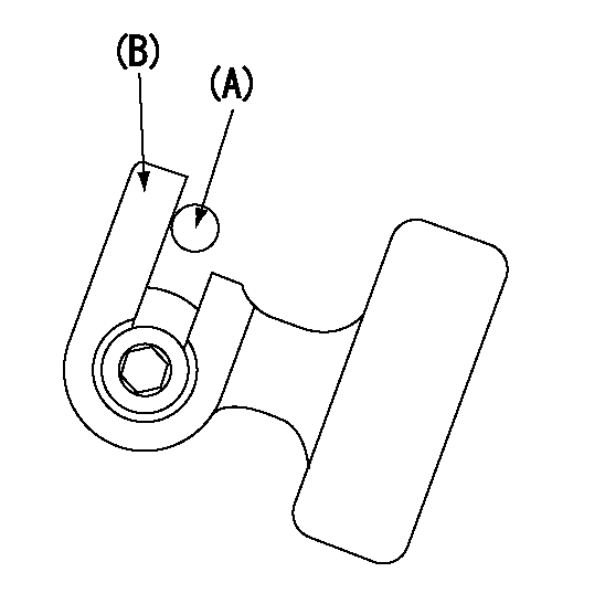
A : Stopper pin
B: Connector
----------
----------
----------
----------
0000001401
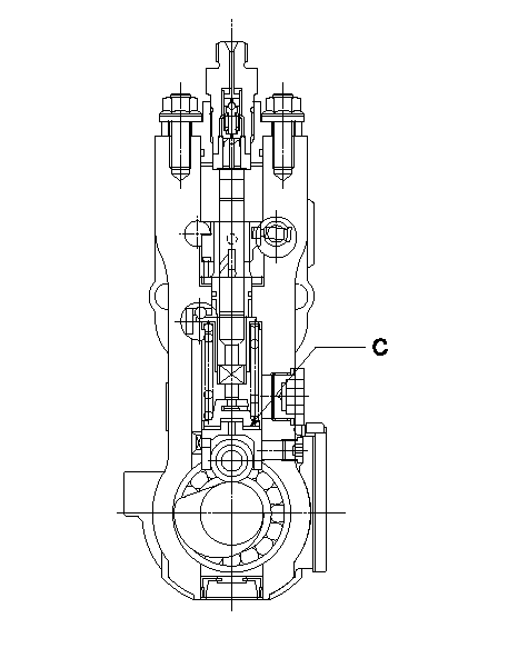
C:Shim
----------
----------
----------
----------
0000001501

A:Sealing position
B:Pre-stroke actuator
1. When installing the pre-stroke actuator on the pump, first tighten the installation bolts loosely, then move the actuator fully counterclockwise (viewed from the drive side).
Temporary tightening torque: 1 - 1.5 N.m (0.1 - 0.15 kgf.m)
2. Move the actuator in the clockwise direction when viewed from the drive side, and adjust so that it becomes the adjustment point of the adjustment value. Then tighten it.
Tightening torque: 7^9 N.m (0.7^0.9 kgf.m)
3. After prestroke actuator installation adjustment, simultaneously stamp both the actuator side and housing side.
----------
----------
----------
----------
0000001701

(PWM) Pulse width modulation (%)
(R) Rack position (mm)
Rack sensor output characteristics
1. Rack limit adjustment
(1)Measure the rack position R2 for PWM a2%.
(2)Confirm that it is within the range R2 = 15+-1 mm.
(3)Measure the rack position R1 at PWM a %.
(4)Confirm that it is within the range R2 - R1 = 10+-0.1 mm.
2. Check the limp home operation.
(1)Move the switch box's limp home switch to the limp home side.
(2)Confirm rack position L1 (mm ) and L2 (mm) for PWM in the above table.
3. Check the pull down operation.
(1)Confirm that the rack position is 19 mm at PWM B%.
(2)In the conditions described in the above table, move the switch box's pull down switch to the pull down side and confirm that the rack position momentarily becomes 1 mm or less.
----------
a1=16.25% a2=72.5% L1=1--mm L2=19++mm A=5% B=95%
----------
----------
a1=16.25% a2=72.5% L1=1--mm L2=19++mm A=5% B=95%
----------
Information:
Additional Parts Needed for Installation
Fluid Property Sensor Mounting Bracket
A mounting bracket must be fabricated to support the Fluid Property Sensor. Since the kit can be used on a large range of engines in both stationary and machine applications, no universal mounting bracket design is possible. A bracket must be field fabricated to allow mounting of the sensor to a structural component of the machine. Leave room for electrical connection and room at each end for Engine Lubricating Oil line connections.Fittings and Adapters
Due to the large range of engines that this system may be used on, a list of all Engine Lubrication Oil line fittings, sizes, styles, and adapters are not possible. As a starting point, the inlet and outlet of the sensor adapter is a 37 degree Flare for 1" oil lines. This must be adapted to the correct size oil line tubing required for each engine. It is likely that the supply and return fuel lines will be of different sizes. It is recommended that the oil line tubing be new and in good condition. The tubing MUST be clean inside. Any small particles that are carried from the inlet hose through the transducer from the system and dislodge the particles. If hoses are equipped with O-ring fittings, the O-rings must be new.Wiring Diagram
Note: During Installation, it is important to protect wiring in key locations. Key locations are any area where the wiring could be nicked or cut and come in contact with the chassis. Avoid installation practices where there could be excessive flexing, chafing, or cutting of the wiring.
Illustration 1 g06137996
Fluid Property Sensor Wiring Schematic
Installation
Machine Preparation
Move the machine to a smooth, level location, and away from other working machines and personnel.
Lower the implements to the ground.
Stop the engine.
Engage the parking brake for the machine.
Place the disconnect switch in the OFF position.
Follow all LOTO instructions for the machine.Installation of the Fluid Property Sensor
The Fluid Property Sensor must be located on a field fabricated bracket in a location of the installer's choice. When selecting a mounting location, the installer must mount the sensor in an area off the engine to reduce vibration of the sensor as well as accessibility of sensor and electrical connection. Electrical connections should avoid sharp bends at connectors, sharp edges, and chafing surfaces. Harnesses should be supported at no less than 30.48 cm (12 inch) intervals. The Fluid Property Sensor must be installed with the orifice opening in the upright position as shown in Illustration 2.
Illustration 2 g06138010
Fluid Property Sensor Installation
(A) Oil Pump
(B) Oil Filter
(C) Engine Oil Gallery
(D) Isolation Valve
(E) Oil Flow
(F) Fluid Property Sensor Orientation
(G) Oil Reservoir
(H) Oil Strainer
(I) Engine Oil SumpInstallation of the Electrical Harnesses
Note: During installation, it is important to protect wiring in key locations. Key locations are any area where the wiring could be nicked or cut and come in contact with the chassis. Avoid installation practices where there could be excessive flexing, chafing, or cutting of the wiring.
Install the 514-3811 Instl GP-Field (Fluid Property Harness) on Fluid Property Sensor.
Route harness back
Have questions with 107691-0190?
Group cross 107691-0190 ZEXEL
107691-0190
INJECTION-PUMP ASSEMBLY