Information injection-pump assembly
BOSCH
9 400 619 945
9400619945
ZEXEL
107492-2164
1074922164
MITSUBISHI
ME015066
me015066

Rating:
You can express buy:
USD 180.8
31-05-2025
31-05-2025
Diesel Fuel Injetion Pump 4PL118 4PL121 for Yunnei 4100QB Zexel 107492-2164 Diesel Injector Pump Kawasaki 49040-7008 Fuel Pump
Service parts 107492-2164 INJECTION-PUMP ASSEMBLY:
1.
_
5.
AUTOM. ADVANCE MECHANIS
6.
COUPLING PLATE
9.
_
11.
Nozzle and Holder
ME015076
12.
Open Pre:MPa(Kqf/cm2)
21.6{220}
15.
NOZZLE SET
Include in #1:
107492-2164
as INJECTION-PUMP ASSEMBLY
Cross reference number
BOSCH
9 400 619 945
9400619945
ZEXEL
107492-2164
1074922164
MITSUBISHI
ME015066
me015066
Zexel num
Bosch num
Firm num
Name
107492-2164
9 400 619 945
ME015066 MITSUBISHI
INJECTION-PUMP ASSEMBLY
4D34T3 K 14CF INJECTION PUMP ASSY TICS MD-TI4 TICS
4D34T3 K 14CF INJECTION PUMP ASSY TICS MD-TI4 TICS
Calibration Data:
Adjustment conditions
Test oil
1404 Test oil ISO4113 or {SAEJ967d}
1404 Test oil ISO4113 or {SAEJ967d}
Test oil temperature
degC
40
40
45
Nozzle and nozzle holder
105780-8250
Bosch type code
1 688 901 101
Nozzle
105780-0120
Bosch type code
1 688 901 990
Nozzle holder
105780-2190
Opening pressure
MPa
20.7
Opening pressure
kgf/cm2
211
Injection pipe
Outer diameter - inner diameter - length (mm) mm 8-3-600
Outer diameter - inner diameter - length (mm) mm 8-3-600
Overflow valve
131425-0520
Overflow valve opening pressure
kPa
255
221
289
Overflow valve opening pressure
kgf/cm2
2.6
2.25
2.95
Tester oil delivery pressure
kPa
255
255
255
Tester oil delivery pressure
kgf/cm2
2.6
2.6
2.6
RED3 control unit part number
407910-3
960
RED3 rack sensor specifications
mm
19
PS/ACT control unit part no.
407910-3
03*
Selector switch no.
02
PS/ACT control unit part no.
407980-2
24*
Digi switch no.
01
Direction of rotation (viewed from drive side)
Right R
Right R
Injection timing adjustment
Direction of rotation (viewed from drive side)
Right R
Right R
Injection order
1-3-4-2
Pre-stroke
mm
5.1
5.07
5.13
Beginning of injection position
Drive side NO.1
Drive side NO.1
Difference between angles 1
Cal 1-3 deg. 90 89.75 90.25
Cal 1-3 deg. 90 89.75 90.25
Difference between angles 2
Cal 1-4 deg. 180 179.75 180.25
Cal 1-4 deg. 180 179.75 180.25
Difference between angles 3
Cyl.1-2 deg. 270 269.75 270.25
Cyl.1-2 deg. 270 269.75 270.25
Injection quantity adjustment
Rack position
(9.9)
Vist
V
2.36
2.36
2.36
Pump speed
r/min
800
800
800
Average injection quantity
mm3/st.
114.5
113.5
115.5
Max. variation between cylinders
%
0
-4
4
Basic
*
PS407980-224*
V
2.25+-0.
01
PS407980-224*
mm
3.1+-0.0
5
PS407910-303*
V
2.25+-0.
01
PS407910-303*
mm
3.1+-0.0
5
Injection quantity adjustment_02
Rack position
(6.1)
Vist
V
2.9
2.8
3
Pump speed
r/min
475
475
475
Average injection quantity
mm3/st.
16
14.5
17.5
Max. variation between cylinders
%
0
-10
10
PS407980-224*
V
V1+0.05+
-0.01
PS407980-224*
mm
5+-0.03
PS407910-303*
V
V1+0.05+
-0.01
PS407910-303*
mm
5+-0.03
Remarks
Refer to items regarding the pre-stroke actuator
Refer to items regarding the pre-stroke actuator
0000001201
CU407980-224*
*
Actuator retarding type
*
Supply voltage
V
12
11.5
12.5
Ambient temperature
degC
23
18
28
Pre-stroke
mm
2
1.95
2.05
Output voltage
V
2.83
2.82
2.84
Adjustment
*
_02
CU407980-224*
*
Supply voltage
V
12
11.5
12.5
Ambient temperature
degC
23
18
28
Pre-stroke
mm
5.1
5.07
5.13
Output voltage
V
1.2
1
1.4
Confirmation
*
Remarks
Output voltage V1
Output voltage V1
_03
CU407980-224*
*
Supply voltage
V
12
11.5
12.5
Ambient temperature
degC
23
18
28
Output voltage
V
3.05
3.05
Confirmation of operating range
*
_04
CU407910-303*
*
Actuator retarding type
*
Supply voltage
V
12
11.5
12.5
Ambient temperature
degC
23
18
28
Pre-stroke
mm
2
1.95
2.05
Output voltage
V
2.83
2.82
2.84
Adjustment
*
_05
CU407910-303*
*
Supply voltage
V
12
11.5
12.5
Ambient temperature
degC
23
18
28
Pre-stroke
mm
5.1
5.07
5.13
Output voltage
V
1.2
1
1.4
Confirmation
*
Remarks
Output voltage V1
Output voltage V1
_06
CU407910-303*
*
Supply voltage
V
12
11.5
12.5
Ambient temperature
degC
23
18
28
Output voltage
V
3.05
3.05
Confirmation of operating range
*
Test data Ex:
Speed control lever angle
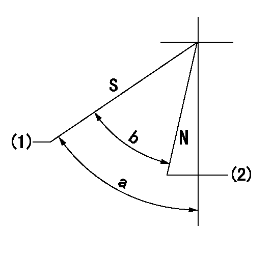
N:Pump normal
S:Stop the pump.
(1)Rack position = aa
(2)Rack position bb
----------
aa=1mm bb=20mm
----------
a=57deg+-5deg b=37deg+-5deg
----------
aa=1mm bb=20mm
----------
a=57deg+-5deg b=37deg+-5deg
0000000901

(1)Pump vertical direction
(2)Position of gear mark '3' at No 1 cylinder's beginning of injection
(3)B.T.D.C.: aa
(4)Pre-stroke: bb
----------
aa=4deg bb=5.1+-0.03mm
----------
a=(130deg)
----------
aa=4deg bb=5.1+-0.03mm
----------
a=(130deg)
Stop lever angle

(1)Pointer
(2)Injection timing aligning mark
(3)Fly weight
(4)The actual shape and direction may be different from this illustration.
Operation sequence
1. Turn the prestroke actuator OFF.
2. Turn the camshaft as far as the No.1 cylinder's beginning of injection position.
3. Check that the pointer alignment mark of the injection pump and the alignment mark of the flywheel are matching.
4. If they are not matching, erase the alignment mark on the flywheel side, and stamp an alignment mark on the flywheel position that matches with the pointer side alignment mark.
5. Check again that the coupling's key groove position is in the No.1 cylinder's beginning of injection position.
----------
----------
----------
----------
0000001301
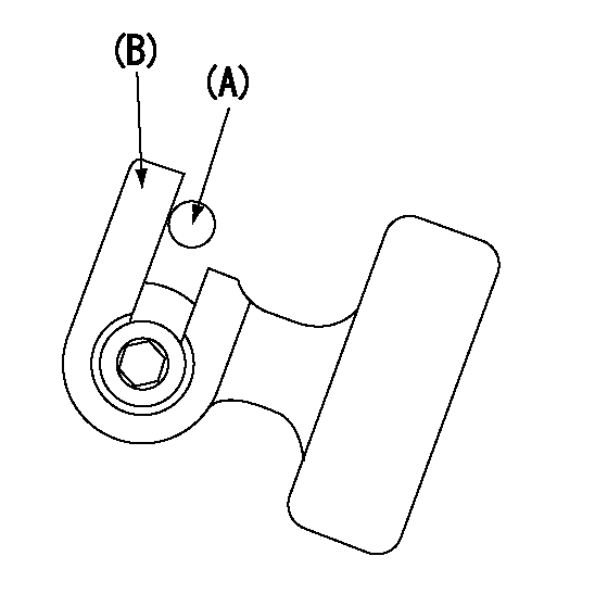
A : Stopper pin
B: Connector
----------
----------
----------
----------
0000001401
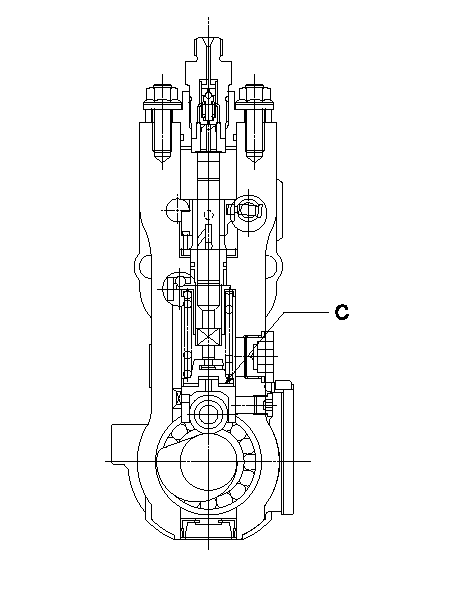
C:Shim
----------
----------
----------
----------
0000001501

A:Sealing position
B:Pre-stroke actuator
1. When installing the pre-stroke actuator on the pump, first tighten the installation bolts loosely, then move the actuator fully counterclockwise (viewed from the drive side).
Temporary tightening torque: 1 - 1.5 N.m (0.1 - 0.15 kgf.m)
2. Move the actuator in the clockwise direction when viewed from the drive side, and adjust so that it becomes the adjustment point of the adjustment value. Then tighten it.
Tightening torque: 7^9 N.m (0.7^0.9 kgf.m)
3. After prestroke actuator installation adjustment, simultaneously stamp both the actuator side and housing side.
----------
----------
----------
----------
0000001701

(Rs) rack sensor specifications
(C/U) control unit part number
(V) Rack sensor output voltage
(R) Rack position (mm)
1. Confirming governor output characteristics (rack 19 mm, span 6 mm)
(1)When the output voltages of the rack sensor are V1 and V2, check that the rack positions R1 and R2 in the table above are satisfied.
----------
----------
----------
----------
0000001901 RACK SENSOR

(VR) measurement voltage
(I) Part number of the control unit
(G) Apply red paint.
(H): End surface of the pump
1. Rack sensor adjustment (154610-0620)
(1)At governor side rack sensor output voltage V1, adjust the bobbin (A) so that the drive side rack sensor output voltage is VR+-0.01.
(2)Apply G at two places.
Connecting part between the joint (B) and the nut (F)
Connecting part between the joint (B) and the end surface of the pump (H)
----------
V1=1.6V
----------
----------
V1=1.6V
----------
Information:
Information Release Memo REM03-33
Reman
December 2003 REMANUFACTURED FUEL INJECTOR FOR VARIOUS 3176C MACHINE APPLICATIONS Announcement The Caterpillar Remanufactured Products Group announces the expansion of the remanufactured injector product line to include coverage for various 3176C Machine applications. Coverage The addition of this injector will provide dealers with an additional repair option to support various 3176C Machine applications where low sulfur fuel is present. Coverage is extensive so please consult your NPR or Reman Cross Reference for exact model coverage. Features And Benefits Cat? Remanufactured injectors offer excellent value to customers. Customers who want fast repair turn-around, superior quality and reliability, and lower repair costs will benefit from the use of these Remanufactured injectors. Cat Remanufactured injectors provide immediate, off-the-shelf availability at a fraction of the new price. Features
All critical engineering changes and updates included
Worldwide availability through Caterpillar? parts distribution system
Backed by Cat warranty Benefits
Improved reliability and performance
Customer access regardless of location
Consistent support Core Acceptance Core Acceptance Criteria for Caterpillar Remanufactured injectors is simple, visual, and requires no special tools. Full core credit is issued when the core is complete, fully assembled, and has an acceptable part number. Consult your Core Acceptance Guide for complete details.Warranty Please consult the appropriate warranty statement for your area.Core Management Please refer to the Caterpillar Core Management Information System (CMIS 2) Parts Information application describing all reman part/CAF and related information. Also refer to other CMIS 2 inquiry applications such as Customer Profiles, Inspection Reason Codes, Inspection Line Inquiry, Add Charge Information, Entitlement Activity, Entitlement Inquiry, CCR Inquiry, CCR Entry, Shipment Processing; Process Packaging Grief; and Reporting to properly manage core returns and monitor inspection performance. This information will be available to all dealers worldwide after your CMIS 2 conversion date. In the meantime, please continue to use the current CMIS Entitlement Parts Inquiry Screen describing the list of parts in a Core Acceptability Family (CAF) and related part number detail.For the latest updates of Reman Policies and Core Management (SELD0122), Core Management Systems & Operations Procedures (SELD0040), and Shipping Instructions (SELD0039), go to the Reman Dealer website https://reman.cat.com If you have any questions regarding core return processing, feel free to call Corinth toll free at (800) 537-2928. For assistance with technical questions, call the Peoria Reman Customer Satisfaction Hot Line also toll free at (888) 88-REMAN or use our E-mail address--Reman_Help.
PELJ0271 CATERPILLAR? ?2003 Caterpillar
Have questions with 107492-2164?
Group cross 107492-2164 ZEXEL
Mitsubishi
107492-2164
9 400 619 945
ME015066
INJECTION-PUMP ASSEMBLY
4D34T3
4D34T3