Information injection-pump assembly
ZEXEL
107492-2081
1074922081
Rating:
Cross reference number
ZEXEL
107492-2081
1074922081
Zexel num
Bosch num
Firm num
Name
107492-2081
INJECTION-PUMP ASSEMBLY
Calibration Data:
Adjustment conditions
Test oil
1404 Test oil ISO4113 or {SAEJ967d}
1404 Test oil ISO4113 or {SAEJ967d}
Test oil temperature
degC
40
40
45
Nozzle and nozzle holder
105780-8250
Bosch type code
1 688 901 101
Nozzle
105780-0120
Bosch type code
1 688 901 990
Nozzle holder
105780-2190
Opening pressure
MPa
20.7
Opening pressure
kgf/cm2
211
Injection pipe
Outer diameter - inner diameter - length (mm) mm 8-3-600
Outer diameter - inner diameter - length (mm) mm 8-3-600
Overflow valve
131425-0520
Overflow valve opening pressure
kPa
255
221
289
Overflow valve opening pressure
kgf/cm2
2.6
2.25
2.95
Tester oil delivery pressure
kPa
255
255
255
Tester oil delivery pressure
kgf/cm2
2.6
2.6
2.6
PS/ACT control unit part no.
407910-3
03*
Selector switch no.
02
PS/ACT control unit part no.
407980-2
24*
Digi switch no.
01
Direction of rotation (viewed from drive side)
Right R
Right R
Injection timing adjustment
Direction of rotation (viewed from drive side)
Right R
Right R
Injection order
1-3-4-2
Pre-stroke
mm
5.6
5.57
5.63
Beginning of injection position
Drive side NO.1
Drive side NO.1
Difference between angles 1
Cal 1-3 deg. 90 89.75 90.25
Cal 1-3 deg. 90 89.75 90.25
Difference between angles 2
Cal 1-4 deg. 180 179.75 180.25
Cal 1-4 deg. 180 179.75 180.25
Difference between angles 3
Cyl.1-2 deg. 270 269.75 270.25
Cyl.1-2 deg. 270 269.75 270.25
Injection quantity adjustment
Adjusting point
-
Rack position
12.8
Pump speed
r/min
800
800
800
Average injection quantity
mm3/st.
104
102.4
105.6
Max. variation between cylinders
%
0
-3
3
Basic
*
Fixing the rack
*
PS407980-224*
V
2.25+-0.
01
PS407980-224*
mm
3.6+-0.0
5
PS407910-303*
V
2.25+-0.
01
PS407910-303*
mm
3.6+-0.0
5
Standard for adjustment of the maximum variation between cylinders
*
Injection quantity adjustment_02
Adjusting point
Z
Rack position
8.4+-0.5
Pump speed
r/min
540
540
540
Average injection quantity
mm3/st.
16
14.5
17.5
Max. variation between cylinders
%
0
-15
15
Fixing the rack
*
PS407980-224*
V
V1+0.05+
-0.01
PS407980-224*
mm
5.5+-0.0
3
PS407910-303*
V
V1+0.05+
-0.01
PS407910-303*
mm
5.5+-0.0
3
Standard for adjustment of the maximum variation between cylinders
*
Remarks
Refer to items regarding the pre-stroke actuator
Refer to items regarding the pre-stroke actuator
Injection quantity adjustment_03
Adjusting point
A
Rack position
R1(12.8)
Pump speed
r/min
800
800
800
Average injection quantity
mm3/st.
104
103
105
Fixing the lever
*
Boost pressure
kPa
52
52
Boost pressure
mmHg
390
390
PS407980-224*
V
2.25+-0.
01
PS407980-224*
mm
3.6+-0.0
5
PS407910-303*
V
2.25+-0.
01
PS407910-303*
mm
3.6+-0.0
5
Injection quantity adjustment_04
Adjusting point
B
Rack position
R1+1.95
Pump speed
r/min
1450
1450
1450
Average injection quantity
mm3/st.
107
103
111
Fixing the lever
*
Boost pressure
kPa
52
52
Boost pressure
mmHg
390
390
PS407980-224*
V
2.25+-0.
01
PS407980-224*
mm
3.6+-0.0
5
PS407910-303*
V
2.25+-0.
01
PS407910-303*
mm
3.6+-0.0
5
Boost compensator adjustment
Pump speed
r/min
550
550
550
Rack position
R2-1
Boost pressure
kPa
22.7
21.4
24
Boost pressure
mmHg
170
160
180
Boost compensator adjustment_02
Pump speed
r/min
550
550
550
Rack position
R2(R1-0.
4)
Boost pressure
kPa
38.7
38.7
38.7
Boost pressure
mmHg
290
290
290
0000001601
CU407980-224*
*
Actuator retarding type
*
Supply voltage
V
12
11.5
12.5
Ambient temperature
degC
23
18
28
Pre-stroke
mm
2.5
2.45
2.55
Output voltage
V
2.83
2.82
2.84
Adjustment
*
_02
CU407980-224*
*
Supply voltage
V
12
11.5
12.5
Ambient temperature
degC
23
18
28
Pre-stroke
mm
5.6
5.57
5.63
Output voltage
V
1.2
1
1.4
Confirmation
*
Remarks
Output voltage V1
Output voltage V1
_03
CU407980-224*
*
Supply voltage
V
12
11.5
12.5
Ambient temperature
degC
23
18
28
Output voltage
V
3.05
3.05
Confirmation of operating range
*
_04
CU407910-303*
*
Actuator retarding type
*
Supply voltage
V
12
11.5
12.5
Ambient temperature
degC
23
18
28
Pre-stroke
mm
2.5
2.45
2.55
Output voltage
V
2.83
2.82
2.84
Adjustment
*
_05
CU407910-303*
*
Supply voltage
V
12
11.5
12.5
Ambient temperature
degC
23
18
28
Pre-stroke
mm
5.6
5.57
5.63
Output voltage
V
1.2
1
1.4
Confirmation
*
Remarks
Output voltage V1
Output voltage V1
_06
CU407910-303*
*
Supply voltage
V
12
11.5
12.5
Ambient temperature
degC
23
18
28
Output voltage
V
3.05
3.05
Confirmation of operating range
*
Test data Ex:
Governor adjustment
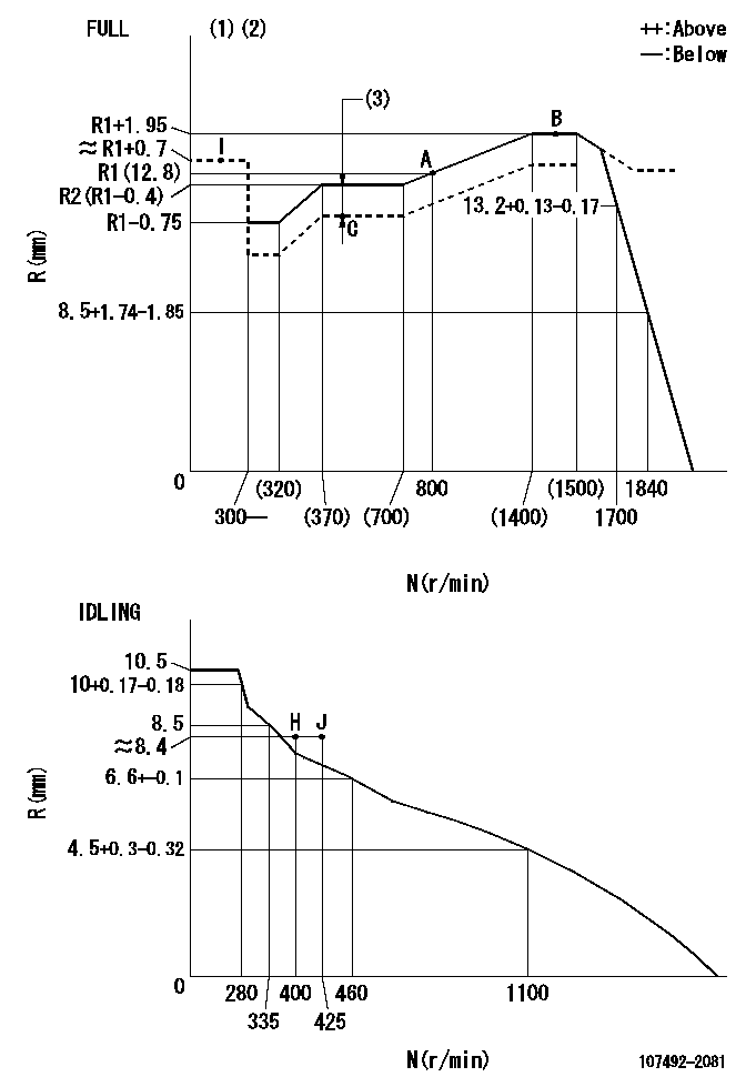
N:Pump speed
R:Rack position (mm)
(1)Torque cam stamping: T1
(2)Tolerance for racks not indicated: +-0.05mm.
(3)Boost compensator stroke: BCL
----------
T1=K28 BCL=1+-0.1mm
----------
----------
T1=K28 BCL=1+-0.1mm
----------
Speed control lever angle

F:Full speed
I:Idle
(1)Use the hole at R = aa
(2)Stopper bolt set position 'H'
----------
aa=40mm
----------
a=22deg+-5deg b=(38deg)+-3deg
----------
aa=40mm
----------
a=22deg+-5deg b=(38deg)+-3deg
Stop lever angle
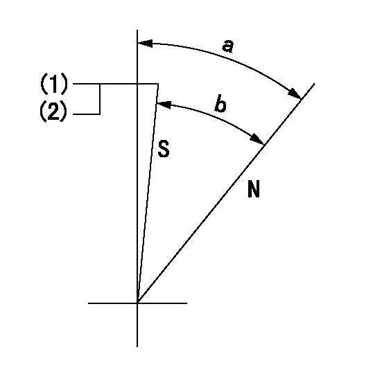
N:Pump normal
S:Stop the pump.
(1)Set the stopper bolt at speed = aa and rack position = bb and confirm non-injection.
(2)After setting the stopper bolt, confirm non-injection at speed cc.
----------
aa=1450r/min bb=6.2-0.5mm cc=350r/min
----------
a=36.5deg+-5deg b=(33deg)+-5deg
----------
aa=1450r/min bb=6.2-0.5mm cc=350r/min
----------
a=36.5deg+-5deg b=(33deg)+-5deg
0000001301

(1)Pump vertical direction
(2)Position of gear mark '3' at No 1 cylinder's beginning of injection
(3)B.T.D.C.: aa
(4)Pre-stroke: bb
----------
aa=7deg bb=5.6+-0.03mm
----------
a=(130deg)
----------
aa=7deg bb=5.6+-0.03mm
----------
a=(130deg)
0000001401

(1)Pointer
(2)Injection timing aligning mark
(3)Fly weight
(4)The actual shape and direction may be different from this illustration.
Operation sequence
1. Turn the prestroke actuator OFF.
2. Turn the camshaft as far as the No.1 cylinder's beginning of injection position.
3. Check that the pointer alignment mark of the injection pump and the alignment mark of the flywheel are matching.
4. If they are not matching, erase the alignment mark on the flywheel side, and stamp an alignment mark on the flywheel position that matches with the pointer side alignment mark.
5. Check again that the coupling's key groove position is in the No.1 cylinder's beginning of injection position.
----------
----------
----------
----------
0000001701
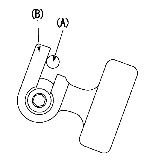
A : Stopper pin
B: Connector
----------
----------
----------
----------
0000001801
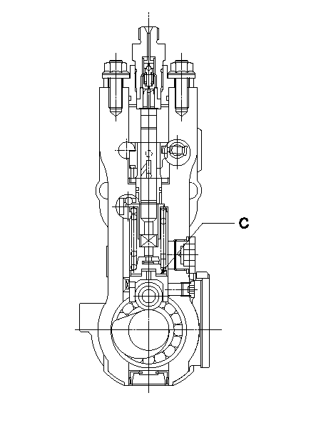
C:Shim
----------
----------
----------
----------
0000001901

A:Sealing position
B:Pre-stroke actuator
1. When installing the pre-stroke actuator on the pump, first tighten the installation bolts loosely, then move the actuator fully counterclockwise (viewed from the drive side).
Temporary tightening torque: 1 - 1.5 N.m (0.1 - 0.15 kgf.m)
2. Move the actuator in the clockwise direction when viewed from the drive side, and adjust so that it becomes the adjustment point of the adjustment value. Then tighten it.
Tightening torque: 7^9 N.m (0.7^0.9 kgf.m)
3. After prestroke actuator installation adjustment, simultaneously stamp both the actuator side and housing side.
----------
----------
----------
----------
0000002201 RACK SENSOR

(VR) measurement voltage
(I) Part number of the control unit
(G) Apply red paint.
(H): End surface of the pump
1. Rack sensor adjustment (-0620)
(1)Fix the speed control lever at the full position
(2)Set the speed to N1 r/min.
(If the boost compensator is provided, apply boost pressure.)
(3)Adjust the bobbin (A) so that the rack sensor's output voltage is VR+-0.01.
(4)At that time, rack position must be Ra.
(5)Apply G at two places.
Connecting part between the joint (B) and the nut (F)
Connecting part between the joint (B) and the end surface of the pump (H)
----------
N1=1450r/min Ra=R1(12.8)+1.95mm
----------
----------
N1=1450r/min Ra=R1(12.8)+1.95mm
----------
Information:
To many, the diesel principle may not be new, however, the special features of Caterpillar Diesel Truck Engines require that the operator and the maintenance personnel become acquainted with the systems in order to give the engine the best possible care. Maximum engine life depends a great deal on a good maintenance schedule performed by reliable personnel with a basic understanding of the working principles and systems.Diesel Engine Principle
This diesel engine operates on the reciprocating piston 4-stroke cycle, compression ignition principle, and burns fuels commercially known as diesel fuels. The basic differences between the spark ignition engine and the diesel engine are; the method of introducing fuel into the system and the method by which the fuel is ignited.The engine always takes a full charge of air into a cylinder on each inlet stroke, compresses it in an extremely small space causing the air to reach temperatures over 1000°F (537°C.). Fuel is injected into the cylinder as the piston nears the top of the compression stroke, where it mixes with the compressed air, and immediately starts to burn. This is called self-ignition, or spontaneous ignition. The expansion of the burning gases forces the piston down on a power stroke. Four Stroke Cycle Principle
The four stroke cycle engine has separate strokes for each basic function. The four strokes and the order in which they occur are: Intake, compression, power and exhaust.It must be remembered that for the four stroke cycle to function the inlet valves, exhaust valves and fuel injection must be timed in proper sequence with the piston. This is accomplished by timing gears between the crankshaft, the valve train and injection pumps. Intake Stroke: As the piston moves down on the inlet stroke, the inlet valve is opened and exhaust valve is closed by the camshaft and rocker arm arrangement. Air is drawn in through the air cleaner and intake valve by the partial vacuum caused by the piston traveling downward. Compression Stroke: At the end of the intake stroke the inlet valve closes and the exhaust valve remains closed. As the piston moves up, the air is compressed into an extremely small space causing the air temperature to rise high enough to ignite fuel. As the piston reaches near the top of the stroke, a measured amount of fuel is injected into the cylinder where it mixes with the compressed air and ignition begins. The atomized and burning fuel then rushes throughout the cylinder above the piston for complete combustion. Power Stroke: The piston is forced down by the pressure of the expanding and burning gases in the cylinder above the piston. During this power stroke, the intake and exhaust valves are closed. Exhaust Stroke: When the piston reaches the bottom of the power stroke the cylinder is filled with burned gases which must be expelled. As the piston begins its upward travel on the exhaust stroke, the exhaust valve is opened by the exhaust lobe on the cam. As the piston moves up, it forces
Have questions with 107492-2081?
Group cross 107492-2081 ZEXEL
107492-2081
INJECTION-PUMP ASSEMBLY