Information injection-pump assembly
ZEXEL
107492-2080
1074922080
Rating:
Cross reference number
ZEXEL
107492-2080
1074922080
Zexel num
Bosch num
Firm num
Name
107492-2080
INJECTION-PUMP ASSEMBLY
Calibration Data:
Adjustment conditions
Test oil
1404 Test oil ISO4113 or {SAEJ967d}
1404 Test oil ISO4113 or {SAEJ967d}
Test oil temperature
degC
40
40
45
Nozzle and nozzle holder
105780-8250
Bosch type code
1 688 901 101
Nozzle
105780-0120
Bosch type code
1 688 901 990
Nozzle holder
105780-2190
Opening pressure
MPa
20.7
Opening pressure
kgf/cm2
211
Injection pipe
Outer diameter - inner diameter - length (mm) mm 8-3-600
Outer diameter - inner diameter - length (mm) mm 8-3-600
Overflow valve
131425-0520
Overflow valve opening pressure
kPa
255
255
255
Overflow valve opening pressure
kgf/cm2
2.6
2.6
2.6
Tester oil delivery pressure
kPa
255
255
255
Tester oil delivery pressure
kgf/cm2
2.6
2.6
2.6
PS/ACT control unit part no.
407910-3
03*
Selector switch no.
02
PS/ACT control unit part no.
407980-2
24*
Digi switch no.
01
Direction of rotation (viewed from drive side)
Right R
Right R
Injection timing adjustment
Direction of rotation (viewed from drive side)
Right R
Right R
Injection order
1-3-4-2
Pre-stroke
mm
5.6
5.57
5.63
Beginning of injection position
Drive side NO.1
Drive side NO.1
Difference between angles 1
Cal 1-3 deg. 90 89.75 90.25
Cal 1-3 deg. 90 89.75 90.25
Difference between angles 2
Cal 1-4 deg. 180 179.75 180.25
Cal 1-4 deg. 180 179.75 180.25
Difference between angles 3
Cyl.1-2 deg. 270 269.75 270.25
Cyl.1-2 deg. 270 269.75 270.25
Injection quantity adjustment
Adjusting point
-
Rack position
15.3
Pump speed
r/min
1450
1450
1450
Average injection quantity
mm3/st.
119
117.4
120.6
Max. variation between cylinders
%
0
-3
3
Basic
*
Fixing the rack
*
PS407980-224*
V
2.25+-0.
01
PS407980-224*
mm
3.6+-0.0
5
PS407910-303*
V
2.25+-0.
01
PS407910-303*
mm
3.6+-0.0
5
Standard for adjustment of the maximum variation between cylinders
*
Injection quantity adjustment_02
Adjusting point
Z
Rack position
8.4+-0.5
Pump speed
r/min
500
500
500
Average injection quantity
mm3/st.
20
18.5
21.5
Max. variation between cylinders
%
0
-15
15
Fixing the rack
*
PS407980-224*
V
V1+0.05+
-0.01
PS407980-224*
mm
5.5+-0.0
3
PS407910-303*
V
V1+0.05+
-0.01
PS407910-303*
mm
5.5+-0.0
3
Standard for adjustment of the maximum variation between cylinders
*
Remarks
Refer to items regarding the pre-stroke actuator
Refer to items regarding the pre-stroke actuator
Injection quantity adjustment_03
Adjusting point
A
Rack position
R1(15.3)
Pump speed
r/min
1450
1450
1450
Average injection quantity
mm3/st.
119
118
120
Fixing the lever
*
Boost pressure
kPa
39.3
39.3
Boost pressure
mmHg
295
295
PS407980-224*
V
2.25+-0.
01
PS407980-224*
mm
3.6+-0.0
5
PS407910-303*
V
2.25+-0.
01
PS407910-303*
mm
3.6+-0.0
5
Injection quantity adjustment_04
Adjusting point
B
Rack position
R1-1.65
Pump speed
r/min
900
900
900
Average injection quantity
mm3/st.
119
115
123
Fixing the lever
*
Boost pressure
kPa
39.3
39.3
Boost pressure
mmHg
295
295
PS407980-224*
V
2.25+-0.
01
PS407980-224*
mm
3.6+-0.0
5
PS407910-303*
V
2.25+-0.
01
PS407910-303*
mm
3.6+-0.0
5
Boost compensator adjustment
Pump speed
r/min
550
550
550
Rack position
R2-1.1
Boost pressure
kPa
8.7
7.4
10
Boost pressure
mmHg
65
55
75
Boost compensator adjustment_02
Pump speed
r/min
550
550
550
Rack position
R2[R1-2.
4]
Boost pressure
kPa
26
26
26
Boost pressure
mmHg
195
195
195
0000001601
CU407980-224*
*
Actuator retarding type
*
Supply voltage
V
12
11.5
12.5
Ambient temperature
degC
23
18
28
Pre-stroke
mm
2.5
2.45
2.55
Output voltage
V
2.83
2.82
2.84
Adjustment
*
_02
CU407980-224*
*
Supply voltage
V
12
11.5
12.5
Ambient temperature
degC
23
18
28
Pre-stroke
mm
5.6
5.57
5.63
Output voltage
V
1.2
1
1.4
Confirmation
*
Remarks
Output voltage V1
Output voltage V1
_03
CU407980-224*
*
Supply voltage
V
12
11.5
12.5
Ambient temperature
degC
23
18
28
Output voltage
V
3.05
3.05
Confirmation of operating range
*
_04
CU407910-303*
*
Actuator retarding type
*
Supply voltage
V
12
11.5
12.5
Ambient temperature
degC
23
18
28
Pre-stroke
mm
2.5
2.45
2.55
Output voltage
V
2.83
2.82
2.84
Adjustment
*
_05
CU407910-303*
*
Supply voltage
V
12
11.5
12.5
Ambient temperature
degC
23
18
28
Pre-stroke
mm
5.6
5.57
5.63
Output voltage
V
1.2
1
1.4
Confirmation
*
Remarks
Output voltage V1
Output voltage V1
_06
CU407910-303*
*
Supply voltage
V
12
11.5
12.5
Ambient temperature
degC
23
18
28
Output voltage
V
3.05
3.05
Confirmation of operating range
*
Test data Ex:
Governor adjustment
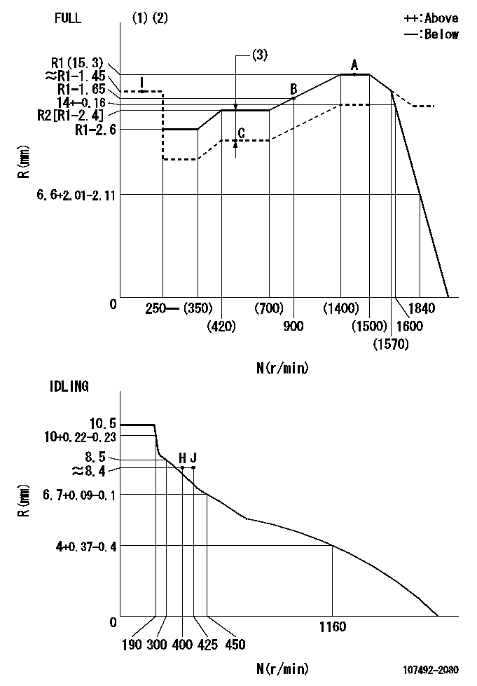
N:Pump speed
R:Rack position (mm)
(1)Torque cam stamping: T1
(2)Tolerance for racks not indicated: +-0.05mm.
(3)Boost compensator stroke: BCL
----------
T1=J91 BCL=1.1+-0.1mm
----------
----------
T1=J91 BCL=1.1+-0.1mm
----------
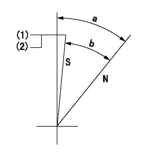
Speed control lever angle

F:Full speed
I:Idle
(1)Use the hole at R = aa
(2)Stopper bolt setting
----------
aa=40mm
----------
a=20deg+-5deg b=(36deg)+-3deg
----------
aa=40mm
----------
a=20deg+-5deg b=(36deg)+-3deg
Stop lever angle
N:Pump normal
S:Stop the pump.
(1)At pump speed aa and rack position bb, set the stopper bolt. Confirm non-injection.
(2)After setting stopper bolt, confirm non-injection at pump speed cc.
----------
aa=1450r/min bb=6.2-0.5mm cc=400r/min
----------
a=36.5deg+-5deg b=(33deg)+-5deg
----------
aa=1450r/min bb=6.2-0.5mm cc=400r/min
----------
a=36.5deg+-5deg b=(33deg)+-5deg
0000001301

(1)Pump vertical direction
(2)Position of gear mark '3' at No 1 cylinder's beginning of injection
(3)B.T.D.C.: aa
(4)Pre-stroke: bb
----------
aa=7deg bb=5.6+-0.03mm
----------
a=(130deg)
----------
aa=7deg bb=5.6+-0.03mm
----------
a=(130deg)
0000001401

(1)Pointer
(2)Injection timing aligning mark
(3)Fly weight
(4)The actual shape and direction may be different from this illustration.
Operation sequence
1. Turn the prestroke actuator OFF.
2. Turn the camshaft as far as the No.1 cylinder's beginning of injection position.
3. Check that the pointer alignment mark of the injection pump and the alignment mark of the flywheel are matching.
4. If they are not matching, erase the alignment mark on the flywheel side, and stamp an alignment mark on the flywheel position that matches with the pointer side alignment mark.
5. Check again that the coupling's key groove position is in the No.1 cylinder's beginning of injection position.
----------
----------
----------
----------
0000001701
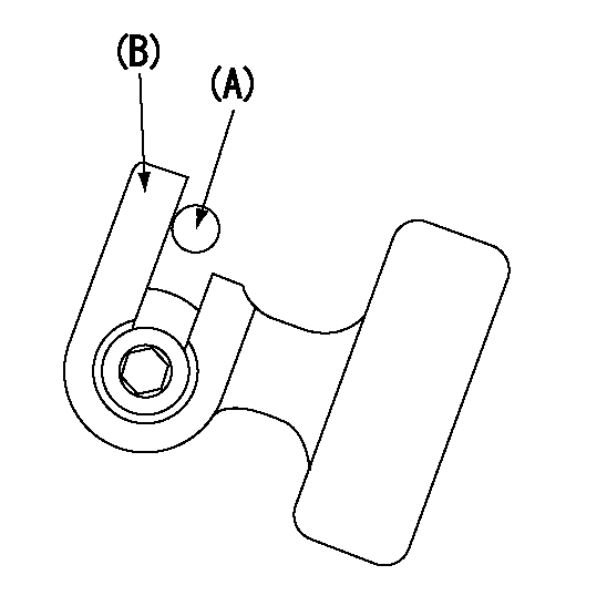
A : Stopper pin
B: Connector
----------
----------
----------
----------
0000001801
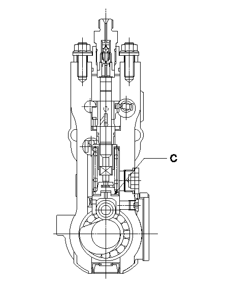
C:Shim
----------
----------
----------
----------
0000001901

A:Sealing position
B:Pre-stroke actuator
1. When installing the pre-stroke actuator on the pump, first tighten the installation bolts loosely, then move the actuator fully counterclockwise (viewed from the drive side).
Temporary tightening torque: 1 - 1.5 N.m (0.1 - 0.15 kgf.m)
2. Move the actuator in the clockwise direction when viewed from the drive side, and adjust so that it becomes the adjustment point of the adjustment value. Then tighten it.
Tightening torque: 7^9 N.m (0.7^0.9 kgf.m)
3. After prestroke actuator installation adjustment, simultaneously stamp both the actuator side and housing side.
----------
----------
----------
----------
0000002201 RACK SENSOR

(VR) measurement voltage
(I) Part number of the control unit
(G) Apply red paint.
(H): End surface of the pump
1. Rack sensor adjustment (-0620)
(1)Fix the speed control lever at the full position
(2)Set the speed to N1 r/min.
(If the boost compensator is provided, apply boost pressure.)
(3)Adjust the bobbin (A) so that the rack sensor's output voltage is VR+-0.01.
(4)At that time, rack position must be Ra.
(5)Apply G at two places.
Connecting part between the joint (B) and the nut (F)
Connecting part between the joint (B) and the end surface of the pump (H)
----------
N1=1450r/min Ra=R1(15.3)mm
----------
----------
N1=1450r/min Ra=R1(15.3)mm
----------
Information:
The following topics describe care and maintenance of the electrical system components. These components functioning together produce the energy needed for operating the electrical equipment on the truck and each is dependent upon the other for satisfactory operation. In the event of failure or improper operation, it is essential to check the entire electrical system as a defect in one component can cause damage to another.Many electrical system problems can be traced to loose or corroded connections. Keep connections tight and make sure the wiring insulation is in satisfactory condition. Most of electrical system testing can be performed on the vehicle. (It should be remembered, if a malfunction is found on a vehicle test, the component may need further testing, repair or replacement.) Installations will have electrical components not furnished by Caterpillar. Consult the vehicle manufacturer's manual for maintenance procedures.Check the electrolyte level of each cell and the general condition of the battery. Maintain the electrolyte level to the base of each vent well. The make-up water must be one of the following (in order of preference): 1. Distilled water.2. Odorless, tasteless drinking water.3. Iron free water.4. Any available water.
Never add acid or electrolyte.
CLEANING BATTERY: Mix a weak solution of baking soda and water. Be careful not to get cleaning solution into battery. Apply the solution with a soft bristle brush.
CLEANING BATTERY TERMINALSThoroughly rinse the battery and battery tray with clean water. Apply grease to the battery cable clamps and terminals and to all threads. Testing The Electrolyte Solution: The general condition of a battery can be determined by measuring the specific gravity of the electrolyte solution and adjusting the reading to 80°F (27°C). If the electrolyte level is too low to allow taking a hydrometer reading, add make-up water to the correct level and then charge the battery 2 to 4 hours before taking a reading.
TESTING ELECTROLYTE SOLUTION1. Insert the hydrometer into a cell. Fill the hydrometer barrel while holding it vertically. The float must not drag on the wall of the barrel.2. Read the hydrometer: 1.250 or above - fully charged battery cell1.250-1.225 - full to half charged battery cell1.225-1.150 - half to low charged battery cellBelow 1.150 - dead cell1.000 - water3. Test each cell in the same manner.4. If there is more than .050 (50 gravity points) variation between the highest and lowest reading, the battery may need to be replaced.5. Adjust the readings to 80°F (27°C). a. For every 10F° (5.5C°) the electrolyte temperature is above 80°F (27°C), add .004 (4 gravity points) to the specific gravity readings.b. For every 10F°(5.5C°) the electrolyte temperature is below 80°F (27°C), subtract .004 (4 gravity points) from the specific gravity reading.The corrected reading is of most importance during cold weather when the hydrometer reading is always corrected to a lower specific gravity reading. A low reading signifies the battery has less available power to crank the engine and that booster batteries may be required. Voltage Test (After Load): A load test should be made on a
Have questions with 107492-2080?
Group cross 107492-2080 ZEXEL
107492-2080
INJECTION-PUMP ASSEMBLY