Information injection-pump assembly
ZEXEL
107492-2072
1074922072

Rating:
Cross reference number
ZEXEL
107492-2072
1074922072
Zexel num
Bosch num
Firm num
Name
107492-2072
INJECTION-PUMP ASSEMBLY
Calibration Data:
Adjustment conditions
Test oil
1404 Test oil ISO4113 or {SAEJ967d}
1404 Test oil ISO4113 or {SAEJ967d}
Test oil temperature
degC
40
40
45
Nozzle and nozzle holder
105780-8250
Bosch type code
1 688 901 101
Nozzle
105780-0120
Bosch type code
1 688 901 990
Nozzle holder
105780-2190
Opening pressure
MPa
20.7
Opening pressure
kgf/cm2
211
Injection pipe
Outer diameter - inner diameter - length (mm) mm 8-3-600
Outer diameter - inner diameter - length (mm) mm 8-3-600
Overflow valve
131425-0520
Overflow valve opening pressure
kPa
255
221
289
Overflow valve opening pressure
kgf/cm2
2.6
2.25
2.95
Tester oil delivery pressure
kPa
255
255
255
Tester oil delivery pressure
kgf/cm2
2.6
2.6
2.6
PS/ACT control unit part no.
407910-3
03*
Selector switch no.
02
PS/ACT control unit part no.
407980-2
24*
Digi switch no.
01
Direction of rotation (viewed from drive side)
Right R
Right R
Injection timing adjustment
Direction of rotation (viewed from drive side)
Right R
Right R
Injection order
1-3-4-2
Pre-stroke
mm
5.6
5.57
5.63
Beginning of injection position
Drive side NO.1
Drive side NO.1
Difference between angles 1
Cal 1-3 deg. 90 89.75 90.25
Cal 1-3 deg. 90 89.75 90.25
Difference between angles 2
Cal 1-4 deg. 180 179.75 180.25
Cal 1-4 deg. 180 179.75 180.25
Difference between angles 3
Cyl.1-2 deg. 270 269.75 270.25
Cyl.1-2 deg. 270 269.75 270.25
Injection quantity adjustment
Adjusting point
-
Rack position
12.3
Pump speed
r/min
800
800
800
Average injection quantity
mm3/st.
110
108.4
111.6
Max. variation between cylinders
%
0
-3
3
Basic
*
Fixing the rack
*
PS407980-224*
V
2.25+-0.
01
PS407980-224*
mm
3.6+-0.0
5
PS407910-303*
V
2.25+-0.
01
PS407910-303*
mm
3.6+-0.0
5
Standard for adjustment of the maximum variation between cylinders
*
Injection quantity adjustment_02
Adjusting point
Z
Rack position
7.5+-0.5
Pump speed
r/min
500
500
500
Average injection quantity
mm3/st.
16
14.5
17.5
Max. variation between cylinders
%
0
-15
15
Fixing the rack
*
PS407980-224*
V
V1+0.05+
-0.01
PS407980-224*
mm
5.5+-0.0
3
PS407910-303*
V
V1+0.05+
-0.01
PS407910-303*
mm
5.5+-0.0
3
Standard for adjustment of the maximum variation between cylinders
*
Remarks
Refer to items regarding the pre-stroke actuator
Refer to items regarding the pre-stroke actuator
Injection quantity adjustment_03
Adjusting point
A
Rack position
R1(12.3)
Pump speed
r/min
800
800
800
Average injection quantity
mm3/st.
110
109
111
Fixing the lever
*
Boost pressure
kPa
43.3
43.3
Boost pressure
mmHg
325
325
PS407980-224*
V
2.25+-0.
01
PS407980-224*
mm
3.6+-0.0
5
PS407910-303*
V
2.25+-0.
01
PS407910-303*
mm
3.6+-0.0
5
Injection quantity adjustment_04
Adjusting point
B
Rack position
R1+2.1
Pump speed
r/min
1450
1450
1450
Average injection quantity
mm3/st.
112.5
108.5
116.5
Fixing the lever
*
Boost pressure
kPa
43.3
43.3
Boost pressure
mmHg
325
325
PS407980-224*
V
2.25+-0.
01
PS407980-224*
mm
3.6+-0.0
5
PS407910-303*
V
2.25+-0.
01
PS407910-303*
mm
3.6+-0.0
5
Boost compensator adjustment
Pump speed
r/min
500
500
500
Rack position
R2-1.4
Boost pressure
kPa
20
18.7
21.3
Boost pressure
mmHg
150
140
160
Boost compensator adjustment_02
Pump speed
r/min
500
500
500
Rack position
R2[R1-0.
4]
Boost pressure
kPa
30
30
30
Boost pressure
mmHg
225
225
225
0000001601
CU407980-224*
*
Actuator retarding type
*
Supply voltage
V
12
11.5
12.5
Ambient temperature
degC
23
18
28
Pre-stroke
mm
2.5
2.45
2.55
Output voltage
V
2.83
2.82
2.84
Adjustment
*
_02
CU407980-224*
*
Supply voltage
V
12
11.5
12.5
Ambient temperature
degC
23
18
28
Pre-stroke
mm
5.6
5.57
5.63
Output voltage
V
1.2
1
1.4
Confirmation
*
Remarks
Output voltage V1
Output voltage V1
_03
CU407980-224*
*
Supply voltage
V
12
11.5
12.5
Ambient temperature
degC
23
18
28
Output voltage
V
3.05
3.05
Confirmation of operating range
*
_04
CU407910-303*
*
Actuator retarding type
*
Supply voltage
V
12
11.5
12.5
Ambient temperature
degC
23
18
28
Pre-stroke
mm
2.5
2.45
2.55
Output voltage
V
2.83
2.82
2.84
Adjustment
*
_05
CU407910-303*
*
Supply voltage
V
12
11.5
12.5
Ambient temperature
degC
23
18
28
Pre-stroke
mm
5.6
5.57
5.63
Output voltage
V
1.2
1
1.4
Confirmation
*
Remarks
Output voltage V1
Output voltage V1
_06
CU407910-303*
*
Supply voltage
V
12
11.5
12.5
Ambient temperature
degC
23
18
28
Output voltage
V
3.05
3.05
Confirmation of operating range
*
Test data Ex:
Governor adjustment
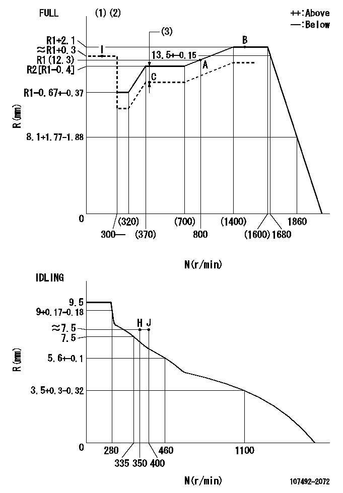
N:Pump speed
R:Rack position (mm)
(1)Torque cam stamping: T1
(2)Tolerance for racks not indicated: +-0.05mm.
(3)Boost compensator stroke: BCL
----------
T1=L04 BCL=1.4+-0.1mm
----------
----------
T1=L04 BCL=1.4+-0.1mm
----------
Speed control lever angle

F:Full speed
I:Idle
(1)Use the hole at R = aa
(2)Stopper bolt setting
----------
aa=40mm
----------
a=25deg+-5deg b=41deg+-3deg
----------
aa=40mm
----------
a=25deg+-5deg b=41deg+-3deg
Stop lever angle
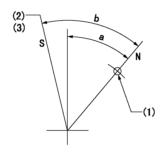
N:Pump normal
S:Stop the pump.
(1)Use the hole at R = aa
(2)Set the stopper screw so that speed = bb and the rack position = cc and confirm non-injection.
(3)After setting the stopper bolt, confirm non-injection at speed dd.
----------
aa=40mm bb=1450r/min cc=1-0.5mm dd=350r/min
----------
a=36.5deg+-5deg b=(45deg)+-5deg
----------
aa=40mm bb=1450r/min cc=1-0.5mm dd=350r/min
----------
a=36.5deg+-5deg b=(45deg)+-5deg
0000001301

(1)Pump vertical direction
(2)Position of gear mark '3' at No 1 cylinder's beginning of injection
(3)B.T.D.C.: aa
(4)Pre-stroke: bb
----------
aa=7deg bb=5.6+-0.03mm
----------
a=(130deg)
----------
aa=7deg bb=5.6+-0.03mm
----------
a=(130deg)
0000001401

(1)Pointer
(2)Injection timing aligning mark
(3)Fly weight
(4)The actual shape and direction may be different from this illustration.
Operation sequence
1. Turn the prestroke actuator OFF.
2. Turn the camshaft as far as the No.1 cylinder's beginning of injection position.
3. Check that the pointer alignment mark of the injection pump and the alignment mark of the flywheel are matching.
4. If they are not matching, erase the alignment mark on the flywheel side, and stamp an alignment mark on the flywheel position that matches with the pointer side alignment mark.
5. Check again that the coupling's key groove position is in the No.1 cylinder's beginning of injection position.
----------
----------
----------
----------
0000001701
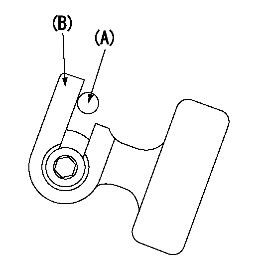
A : Stopper pin
B: Connector
----------
----------
----------
----------
0000001801
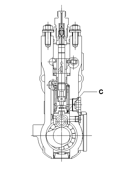
C:Shim
----------
----------
----------
----------
0000001901

A:Sealing position
B:Pre-stroke actuator
1. When installing the pre-stroke actuator on the pump, first tighten the installation bolts loosely, then move the actuator fully counterclockwise (viewed from the drive side).
Temporary tightening torque: 1 - 1.5 N.m (0.1 - 0.15 kgf.m)
2. Move the actuator in the clockwise direction when viewed from the drive side, and adjust so that it becomes the adjustment point of the adjustment value. Then tighten it.
Tightening torque: 7^9 N.m (0.7^0.9 kgf.m)
3. After prestroke actuator installation adjustment, simultaneously stamp both the actuator side and housing side.
----------
----------
----------
----------
0000002201 RACK SENSOR

(VR) measurement voltage
(I) Part number of the control unit
(G) Apply red paint.
(H): End surface of the pump
1. Rack sensor adjustment (-0620)
(1)Fix the speed control lever at the full position
(2)Set the speed to N1 r/min.
(If the boost compensator is provided, apply boost pressure.)
(3)Adjust the bobbin (A) so that the rack sensor's output voltage is VR+-0.01.
(4)At that time, rack position must be Ra.
(5)Apply G at two places.
Connecting part between the joint (B) and the nut (F)
Connecting part between the joint (B) and the end surface of the pump (H)
----------
N1=1450r/min Ra=R1(12.3)+2.1mm
----------
----------
N1=1450r/min Ra=R1(12.3)+2.1mm
----------
Information:
General Instructions
These instructions are a review of many items which a serviceman encounters in servicing and maintaining a truck engine.PROBLEM ANALYZING: In analyzing a system malfunction, use this systematic procedure to locate and correct the problem.1. Determine problem.2. List possible causes.3. Devise checks.4. Conduct checks in logical order to determine cause.5. Consider remaining service life against cost of parts and labor.6. Make necessary repair.7. Recheck.SAFETY: Your safety and that of others is always the number one consideration when servicing or maintaining trucks and truck engines. Safety is a matter of thoroughly understanding the job to be done and the application of good common sense. It is not just a matter of "do's" and "don'ts".CLEANLINESS: The most important single item in assuring long engine life is to keep dirt out of vital working parts. Precautions have been taken to safeguard against this. Enclosed compartments, seals and filters have been provided to keep the supply of air, fuel, coolant and lubricants clean. It is important that these safeguards be maintained.Whenever fuel, lubricating oil, coolant lines or air lines are disconnected, clean the point of disconnection as well as the adjacent area. As soon as the disconnection is made, cap, plug or tape the line or opening to prevent entry of foreign material. The same recommendations for cleaning and covering apply when access covers or inspection plates are removed.Clean and inspect all parts. Be sure all passages and holes are open. Cover all parts to keep them clean. Be sure parts are clean when they are installed. Leave new parts in their containers until ready for assembly.REMOVAL AND INSTALLATION: Use a hoist to remove heavy components. Engine removal should be accomplished by using an adjustable lifting beam. All supporting members (chains and cables) should be parallel to each other and as near perpendicular as possible to the top of the object being lifted. When it is necessary to remove a component on an angle, remember that the capacity of an eyebolt diminishes as the angle between the supporting members and the object becomes less than 90°. Eyebolts and brackets should never be bent and should only have stress in tension.Some removals require the use of lifting fixtures to obtain proper balance and to provide safe handling.If a part resists removal, check to be certain all nuts and bolts have been removed and that an adjacent part is not interfering.DISASSEMBLY AND ASSEMBLY: When servicing or repairing the engine, complete each step in turn. Do not partially assemble one part and start assembling some other part. Make all adjustments as recommended. Always check the job after it is completed to see nothing has been overlooked.BOLTS AND BOLT TORQUE: Use bolts of the correct length. A bolt which is too long may "bottom" before the head is tight against the part it is to hold and cause failure. The threads in the assembly can also become damaged when a "long" bolt is used.If a bolt is too short, there may not be enough threads
These instructions are a review of many items which a serviceman encounters in servicing and maintaining a truck engine.PROBLEM ANALYZING: In analyzing a system malfunction, use this systematic procedure to locate and correct the problem.1. Determine problem.2. List possible causes.3. Devise checks.4. Conduct checks in logical order to determine cause.5. Consider remaining service life against cost of parts and labor.6. Make necessary repair.7. Recheck.SAFETY: Your safety and that of others is always the number one consideration when servicing or maintaining trucks and truck engines. Safety is a matter of thoroughly understanding the job to be done and the application of good common sense. It is not just a matter of "do's" and "don'ts".CLEANLINESS: The most important single item in assuring long engine life is to keep dirt out of vital working parts. Precautions have been taken to safeguard against this. Enclosed compartments, seals and filters have been provided to keep the supply of air, fuel, coolant and lubricants clean. It is important that these safeguards be maintained.Whenever fuel, lubricating oil, coolant lines or air lines are disconnected, clean the point of disconnection as well as the adjacent area. As soon as the disconnection is made, cap, plug or tape the line or opening to prevent entry of foreign material. The same recommendations for cleaning and covering apply when access covers or inspection plates are removed.Clean and inspect all parts. Be sure all passages and holes are open. Cover all parts to keep them clean. Be sure parts are clean when they are installed. Leave new parts in their containers until ready for assembly.REMOVAL AND INSTALLATION: Use a hoist to remove heavy components. Engine removal should be accomplished by using an adjustable lifting beam. All supporting members (chains and cables) should be parallel to each other and as near perpendicular as possible to the top of the object being lifted. When it is necessary to remove a component on an angle, remember that the capacity of an eyebolt diminishes as the angle between the supporting members and the object becomes less than 90°. Eyebolts and brackets should never be bent and should only have stress in tension.Some removals require the use of lifting fixtures to obtain proper balance and to provide safe handling.If a part resists removal, check to be certain all nuts and bolts have been removed and that an adjacent part is not interfering.DISASSEMBLY AND ASSEMBLY: When servicing or repairing the engine, complete each step in turn. Do not partially assemble one part and start assembling some other part. Make all adjustments as recommended. Always check the job after it is completed to see nothing has been overlooked.BOLTS AND BOLT TORQUE: Use bolts of the correct length. A bolt which is too long may "bottom" before the head is tight against the part it is to hold and cause failure. The threads in the assembly can also become damaged when a "long" bolt is used.If a bolt is too short, there may not be enough threads
Have questions with 107492-2072?
Group cross 107492-2072 ZEXEL
107492-2072
INJECTION-PUMP ASSEMBLY