Information injection-pump assembly
ZEXEL
107492-2071
1074922071

Rating:
Cross reference number
ZEXEL
107492-2071
1074922071
Zexel num
Bosch num
Firm num
Name
107492-2071
INJECTION-PUMP ASSEMBLY
Calibration Data:
Adjustment conditions
Test oil
1404 Test oil ISO4113 or {SAEJ967d}
1404 Test oil ISO4113 or {SAEJ967d}
Test oil temperature
degC
40
40
45
Nozzle and nozzle holder
105780-8250
Bosch type code
1 688 901 101
Nozzle
105780-0120
Bosch type code
1 688 901 990
Nozzle holder
105780-2190
Opening pressure
MPa
20.7
Opening pressure
kgf/cm2
211
Injection pipe
Outer diameter - inner diameter - length (mm) mm 8-3-600
Outer diameter - inner diameter - length (mm) mm 8-3-600
Overflow valve
131425-0520
Overflow valve opening pressure
kPa
255
221
289
Overflow valve opening pressure
kgf/cm2
2.6
2.25
2.95
Tester oil delivery pressure
kPa
255
255
255
Tester oil delivery pressure
kgf/cm2
2.6
2.6
2.6
PS/ACT control unit part no.
407910-3
03*
Selector switch no.
02
PS/ACT control unit part no.
407980-2
24*
Digi switch no.
01
Direction of rotation (viewed from drive side)
Right R
Right R
Injection timing adjustment
Direction of rotation (viewed from drive side)
Right R
Right R
Injection order
1-3-4-2
Pre-stroke
mm
5.6
5.57
5.63
Beginning of injection position
Drive side NO.1
Drive side NO.1
Difference between angles 1
Cal 1-3 deg. 90 89.75 90.25
Cal 1-3 deg. 90 89.75 90.25
Difference between angles 2
Cal 1-4 deg. 180 179.75 180.25
Cal 1-4 deg. 180 179.75 180.25
Difference between angles 3
Cyl.1-2 deg. 270 269.75 270.25
Cyl.1-2 deg. 270 269.75 270.25
Injection quantity adjustment
Adjusting point
-
Rack position
12.8
Pump speed
r/min
800
800
800
Average injection quantity
mm3/st.
104
102.4
105.6
Max. variation between cylinders
%
0
-3
3
Basic
*
Fixing the rack
*
PS407980-224*
V
2.25+-0.
01
PS407980-224*
mm
3.6+-0.0
5
PS407910-303*
V
2.25+-0.
01
PS407910-303*
mm
3.6+-0.0
5
Standard for adjustment of the maximum variation between cylinders
*
Injection quantity adjustment_02
Adjusting point
Z
Rack position
8.5+-0.5
Pump speed
r/min
500
500
500
Average injection quantity
mm3/st.
16
14.5
17.5
Max. variation between cylinders
%
0
-15
15
Fixing the rack
*
PS407980-224*
V
V1+0.05+
-0.01
PS407980-224*
mm
5.5+-0.0
3
PS407910-303*
V
V1+0.05+
-0.01
PS407910-303*
mm
5.5+-0.0
3
Standard for adjustment of the maximum variation between cylinders
*
Remarks
Refer to items regarding the pre-stroke actuator
Refer to items regarding the pre-stroke actuator
Injection quantity adjustment_03
Adjusting point
A
Rack position
R1(12.8)
Pump speed
r/min
800
800
800
Average injection quantity
mm3/st.
104
103
105
Fixing the lever
*
Boost pressure
kPa
52
52
Boost pressure
mmHg
390
390
PS407980-224*
V
2.25+-0.
01
PS407980-224*
mm
3.6+-0.0
5
PS407910-303*
V
2.25+-0.
01
PS407910-303*
mm
3.6+-0.0
5
Injection quantity adjustment_04
Adjusting point
B
Rack position
R1+1.95
Pump speed
r/min
1450
1450
1450
Average injection quantity
mm3/st.
107
103
111
Fixing the lever
*
Boost pressure
kPa
52
52
Boost pressure
mmHg
390
390
PS407980-224*
V
2.25+-0.
01
PS407980-224*
mm
3.6+-0.0
5
PS407910-303*
V
2.25+-0.
01
PS407910-303*
mm
3.6+-0.0
5
Boost compensator adjustment
Pump speed
r/min
550
550
550
Rack position
R2-1
Boost pressure
kPa
22.7
21.4
24
Boost pressure
mmHg
170
160
180
Boost compensator adjustment_02
Pump speed
r/min
550
550
550
Rack position
R2(R1-0.
4)
Boost pressure
kPa
38.7
38.7
38.7
Boost pressure
mmHg
290
290
290
0000001601
CU407980-224*
*
Actuator retarding type
*
Supply voltage
V
12
11.5
12.5
Ambient temperature
degC
23
18
28
Pre-stroke
mm
2.5
2.45
2.55
Output voltage
V
2.83
2.82
2.84
Adjustment
*
_02
CU407980-224*
*
Supply voltage
V
12
11.5
12.5
Ambient temperature
degC
23
18
28
Pre-stroke
mm
5.6
5.57
5.63
Output voltage
V
1.2
1
1.4
Confirmation
*
Remarks
Output voltage V1
Output voltage V1
_03
CU407980-224*
*
Supply voltage
V
12
11.5
12.5
Ambient temperature
degC
23
18
28
Output voltage
V
3.05
3.05
Confirmation of operating range
*
_04
CU407910-303*
*
Actuator retarding type
*
Supply voltage
V
12
11.5
12.5
Ambient temperature
degC
23
18
28
Pre-stroke
mm
2.5
2.45
2.55
Output voltage
V
2.83
2.82
2.84
Adjustment
*
_05
CU407910-303*
*
Supply voltage
V
12
11.5
12.5
Ambient temperature
degC
23
18
28
Pre-stroke
mm
5.6
5.57
5.63
Output voltage
V
1.2
1
1.4
Confirmation
*
Remarks
Output voltage V1
Output voltage V1
_06
CU407910-303*
*
Supply voltage
V
12
11.5
12.5
Ambient temperature
degC
23
18
28
Output voltage
V
3.05
3.05
Confirmation of operating range
*
Test data Ex:
Governor adjustment
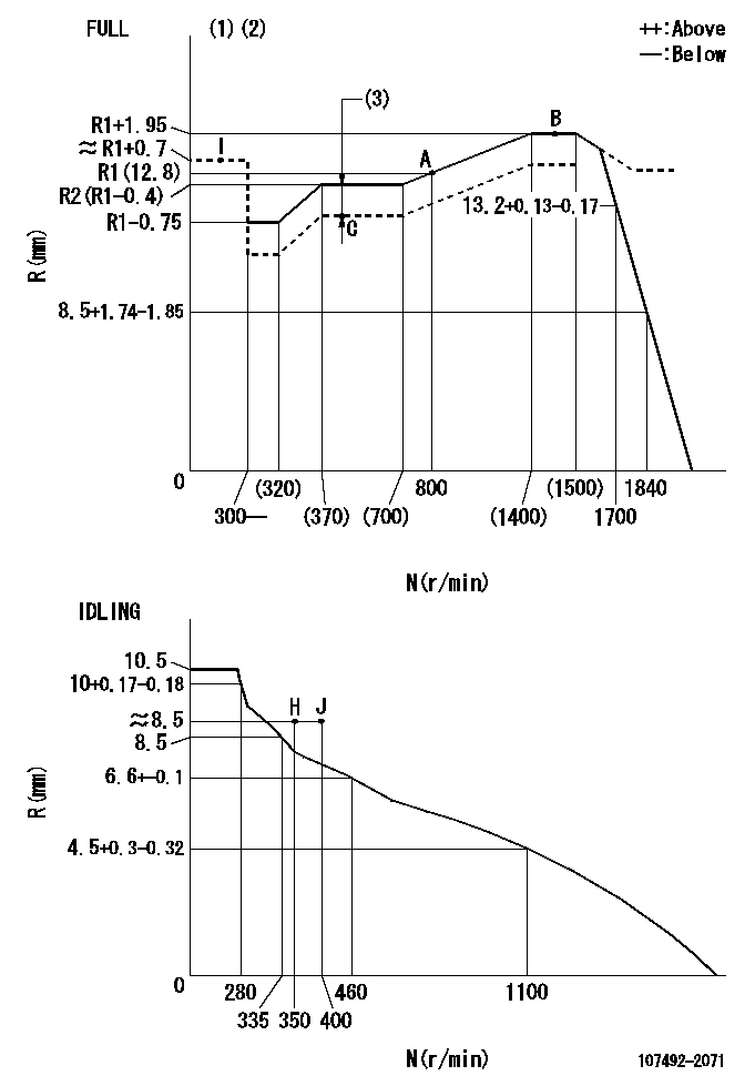
N:Pump speed
R:Rack position (mm)
(1)Torque cam stamping: T1
(2)Tolerance for racks not indicated: +-0.05mm.
(3)Boost compensator stroke: BCL
----------
T1=K28 BCL=1+-0.1mm
----------
----------
T1=K28 BCL=1+-0.1mm
----------
Speed control lever angle

F:Full speed
I:Idle
(1)Use the hole at R = aa
(2)Stopper bolt set position 'H'
----------
aa=40mm
----------
a=25deg+-5deg b=(41deg)+-3deg
----------
aa=40mm
----------
a=25deg+-5deg b=(41deg)+-3deg
Stop lever angle
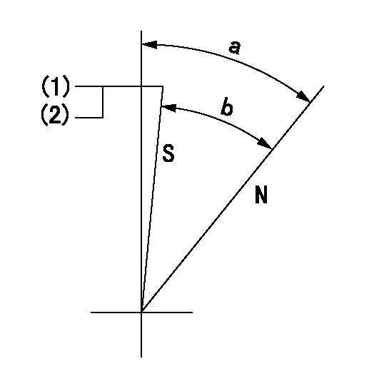
N:Pump normal
S:Stop the pump.
(1)Set the stopper bolt at speed = aa and rack position = bb and confirm non-injection.
(2)After setting the stopper bolt, confirm non-injection at speed cc.
----------
aa=1450r/min bb=6.2-0.5mm cc=350r/min
----------
a=36.5deg+-5deg b=(33deg)+-5deg
----------
aa=1450r/min bb=6.2-0.5mm cc=350r/min
----------
a=36.5deg+-5deg b=(33deg)+-5deg
0000001301

(1)Pump vertical direction
(2)Position of gear mark '3' at No 1 cylinder's beginning of injection
(3)B.T.D.C.: aa
(4)Pre-stroke: bb
----------
aa=7deg bb=5.6+-0.03mm
----------
a=(130deg)
----------
aa=7deg bb=5.6+-0.03mm
----------
a=(130deg)
0000001401

(1)Pointer
(2)Injection timing aligning mark
(3)Fly weight
(4)The actual shape and direction may be different from this illustration.
Operation sequence
1. Turn the prestroke actuator OFF.
2. Turn the camshaft as far as the No.1 cylinder's beginning of injection position.
3. Check that the pointer alignment mark of the injection pump and the alignment mark of the flywheel are matching.
4. If they are not matching, erase the alignment mark on the flywheel side, and stamp an alignment mark on the flywheel position that matches with the pointer side alignment mark.
5. Check again that the coupling's key groove position is in the No.1 cylinder's beginning of injection position.
----------
----------
----------
----------
0000001701
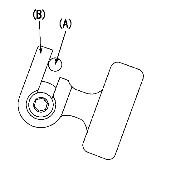
A : Stopper pin
B: Connector
----------
----------
----------
----------
0000001801
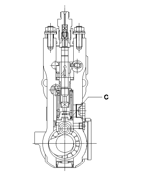
C:Shim
----------
----------
----------
----------
0000001901

A:Sealing position
B:Pre-stroke actuator
1. When installing the pre-stroke actuator on the pump, first tighten the installation bolts loosely, then move the actuator fully counterclockwise (viewed from the drive side).
Temporary tightening torque: 1 - 1.5 N.m (0.1 - 0.15 kgf.m)
2. Move the actuator in the clockwise direction when viewed from the drive side, and adjust so that it becomes the adjustment point of the adjustment value. Then tighten it.
Tightening torque: 7^9 N.m (0.7^0.9 kgf.m)
3. After prestroke actuator installation adjustment, simultaneously stamp both the actuator side and housing side.
----------
----------
----------
----------
0000002201 RACK SENSOR

(VR) measurement voltage
(I) Part number of the control unit
(G) Apply red paint.
(H): End surface of the pump
1. Rack sensor adjustment (-0620)
(1)Fix the speed control lever at the full position
(2)Set the speed to N1 r/min.
(If the boost compensator is provided, apply boost pressure.)
(3)Adjust the bobbin (A) so that the rack sensor's output voltage is VR+-0.01.
(4)At that time, rack position must be Ra.
(5)Apply G at two places.
Connecting part between the joint (B) and the nut (F)
Connecting part between the joint (B) and the end surface of the pump (H)
----------
N1=1450r/min Ra=R1(12.8)+1.95mm
----------
----------
N1=1450r/min Ra=R1(12.8)+1.95mm
----------
Information:
No. 2D diesel fuel is recommended for use in the 1100 Series Caterpillar Diesel Truck Engines, although No. 1D may be used if desired.In selecting a fuel, note that distillate fuels are especially desirable because the fuel is heated to a vaporous state and condensed, thus eliminating all sediment and residue.There is considerable variation in the composition of fuels distributed under the No. 2D grade classifications. For desirable engine service it is most important to give special attention to cetane no., water and sediment, pour point, cloud point and sulphur content. USE FUELS WHICH MEET THE FOLLOWING REQUIREMENTS:Cetane No. ... 40 minimumWater and Sediment ... 0.1% maximumPour Point ... 10F° (-12C°) below ambient temperatureCloud Point ... No higher than ambient temperatureSulphur Content ... Above 0.4% adjust oil change periodGravity ... 32-40 A.P.I. at 60°F (16°C) Cetane No.: This is an indication of a fuel's ignition quality and should not be less than 40 for this engine. For high altitude operation or cold weather starting, a higher cetane number is required. Water and Sediment: A good clean fuel will contain no more than .1% sediment and water. Dirty fuels lead to early filter plugging and in addition can result in the formation or gums and resins reducing filter and engine life. Pour Point: The pour point of the fuel has no effect on engine performance, as long as the fuel is fluid enough to flow from the fuel tank to the engine. The pour point of the fuel should be at least 10F° (-12°C) below the lowest atmospheric temperature at which the engine must start and operate. In extremely cold temperatures it may be necessary to use No. 1D diesel fuel. Cloud Point: Cloud point is the temperature at which wax crystals become visible and is generally above the pour point of the fuel. The cloud point should be no higher than the lowest atmospheric temperature at which the engine must start to keep the fuel filter elements from plugging with wax crystals. Sulphur Content: As sulphur content increases, the crankcase oil change periods should be reduced. Fuel containing 0.4% or less sulphur content, use normal oil change periods. If the fuel contains 0.4% to 1.0% sulphur, oil change periods should be reduced to one-half normal interval. If the fuel contains more than 1.0% sulphur, oil change periods should be reduced to one-fourth normal interval. Gravity: Gravity is the measurement of heat units in a certain amount of fuel. The heavier the fuel (the lower the number) the more heat units per volume. If a fuel with a higher A.P.I. gravity is used the power produced will be lower. Select fuels with the lower A.P.I. gravity reading.Authorized dealers are familiar with fuels that have given good results in Caterpillar Diesel Engines and should be consulted regarding the fuel to use.
Have questions with 107492-2071?
Group cross 107492-2071 ZEXEL
107492-2071
INJECTION-PUMP ASSEMBLY