Information injection-pump assembly
BOSCH
9 400 618 828
9400618828
ZEXEL
107492-0050
1074920050
NISSAN-DIESEL
1670030D11
1670030d11
Rating:
Cross reference number
BOSCH
9 400 618 828
9400618828
ZEXEL
107492-0050
1074920050
NISSAN-DIESEL
1670030D11
1670030d11
Zexel num
Bosch num
Firm num
Name
Calibration Data:
Adjustment conditions
Test oil
1404 Test oil ISO4113 or {SAEJ967d}
1404 Test oil ISO4113 or {SAEJ967d}
Test oil temperature
degC
40
40
45
Nozzle and nozzle holder
105780-8250
Bosch type code
1 688 901 101
Nozzle
105780-0120
Bosch type code
1 688 901 990
Nozzle holder
105780-2190
Opening pressure
MPa
20.7
Opening pressure
kgf/cm2
211
Injection pipe
Outer diameter - inner diameter - length (mm) mm 8-3-600
Outer diameter - inner diameter - length (mm) mm 8-3-600
Overflow valve
131425-0520
Overflow valve opening pressure
kPa
255
221
289
Overflow valve opening pressure
kgf/cm2
2.6
2.25
2.95
Tester oil delivery pressure
kPa
255
255
255
Tester oil delivery pressure
kgf/cm2
2.6
2.6
2.6
PS/ACT control unit part no.
407910-3
03*
Selector switch no.
02
PS/ACT control unit part no.
407980-2
24*
Digi switch no.
01
Direction of rotation (viewed from drive side)
Right R
Right R
Injection timing adjustment
Direction of rotation (viewed from drive side)
Right R
Right R
Injection order
1-3-4-2
Pre-stroke
mm
5.6
5.57
5.63
Beginning of injection position
Drive side NO.1
Drive side NO.1
Difference between angles 1
Cal 1-3 deg. 90 89.75 90.25
Cal 1-3 deg. 90 89.75 90.25
Difference between angles 2
Cal 1-4 deg. 180 179.75 180.25
Cal 1-4 deg. 180 179.75 180.25
Difference between angles 3
Cyl.1-2 deg. 270 269.75 270.25
Cyl.1-2 deg. 270 269.75 270.25
Injection quantity adjustment
Adjusting point
-
Rack position
13.9
Pump speed
r/min
900
900
900
Average injection quantity
mm3/st.
104.5
102.5
106.5
Max. variation between cylinders
%
0
-4
4
Basic
*
Fixing the rack
*
PS407980-224*
V
2.25+-0.
01
PS407980-224*
mm
3.6+-0.0
5
PS407910-303*
V
2.25+-0.
01
PS407910-303*
mm
3.6+-0.0
5
Standard for adjustment of the maximum variation between cylinders
*
Injection quantity adjustment_02
Adjusting point
Z
Rack position
7.5+-0.5
Pump speed
r/min
550
550
550
Average injection quantity
mm3/st.
12
10.2
13.8
Max. variation between cylinders
%
0
-10
10
Fixing the rack
*
PS407980-224*
V
V1+0.05+
-0.01
PS407980-224*
mm
5.5+-0.0
3
PS407910-303*
V
V1+0.05+
-0.01
PS407910-303*
mm
5.5+-0.0
3
Standard for adjustment of the maximum variation between cylinders
*
Remarks
Refer to items regarding the pre-stroke actuator
Refer to items regarding the pre-stroke actuator
Injection quantity adjustment_03
Adjusting point
A
Rack position
R1(13.9)
Pump speed
r/min
900
900
900
Average injection quantity
mm3/st.
104.5
103.5
105.5
Basic
*
Fixing the lever
*
Boost pressure
kPa
60
60
Boost pressure
mmHg
450
450
PS407980-224*
V
2.25+-0.
01
PS407980-224*
mm
3.6+-0.0
5
PS407910-303*
V
2.25+-0.
01
PS407910-303*
mm
3.6+-0.0
5
Injection quantity adjustment_04
Adjusting point
B
Rack position
R1+3.15
Pump speed
r/min
1400
1400
1400
Average injection quantity
mm3/st.
120.5
116.5
124.5
Fixing the lever
*
Boost pressure
kPa
60
60
Boost pressure
mmHg
450
450
PS407980-224*
V
2.25+-0.
01
PS407980-224*
mm
3.6+-0.0
5
PS407910-303*
V
2.25+-0.
01
PS407910-303*
mm
3.6+-0.0
5
Injection quantity adjustment_05
Adjusting point
C
Rack position
R2-2.85
Pump speed
r/min
500
500
500
Average injection quantity
mm3/st.
48.7
44.7
52.7
Fixing the lever
*
Boost pressure
kPa
0
0
0
Boost pressure
mmHg
0
0
0
PS407980-224*
V
2.25+-0.
01
PS407980-224*
mm
3.6+-0.0
5
PS407910-303*
V
2.25+-0.
01
PS407910-303*
mm
3.6+-0.0
5
Boost compensator adjustment
Pump speed
r/min
500
500
500
Rack position
R2-2.85
Boost pressure
kPa
6.7
5.4
8
Boost pressure
mmHg
50
40
60
Boost compensator adjustment_02
Pump speed
r/min
500
500
500
Rack position
R2(R1-1.
25)
Boost pressure
kPa
46.7
46.7
46.7
Boost pressure
mmHg
350
350
350
0000001601
CU407980-224*
*
Actuator retarding type
*
Supply voltage
V
12
11.5
12.5
Ambient temperature
degC
23
18
28
Pre-stroke
mm
2.5
2.45
2.55
Output voltage
V
2.83
2.82
2.84
Adjustment
*
_02
CU407980-224*
*
Supply voltage
V
12
11.5
12.5
Ambient temperature
degC
23
18
28
Pre-stroke
mm
5.6
5.57
5.63
Output voltage
V
1.2
1
1.4
Confirmation
*
Remarks
Output voltage V1
Output voltage V1
_03
CU407980-224*
*
Supply voltage
V
12
11.5
12.5
Ambient temperature
degC
23
18
28
Output voltage
V
3.05
3.05
Confirmation of operating range
*
_04
CU407910-303*
*
Actuator retarding type
*
Supply voltage
V
12
11.5
12.5
Ambient temperature
degC
23
18
28
Pre-stroke
mm
2.5
2.45
2.55
Output voltage
V
2.83
2.82
2.84
Adjustment
*
_05
CU407910-303*
*
Supply voltage
V
12
11.5
12.5
Ambient temperature
degC
23
18
28
Pre-stroke
mm
5.6
5.57
5.63
Output voltage
V
1.2
1
1.4
Confirmation
*
Remarks
Output voltage V1
Output voltage V1
_06
CU407910-303*
*
Supply voltage
V
12
11.5
12.5
Ambient temperature
degC
23
18
28
Output voltage
V
2.83
2.82
2.84
Confirmation of operating range
*
Test data Ex:
Governor adjustment
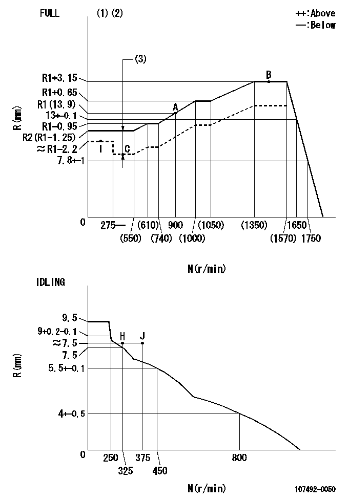
N:Pump speed
R:Rack position (mm)
(1)Torque cam stamping: T1
(2)Tolerance for racks not indicated: +-0.05mm.
(3)Boost compensator stroke: BCL
----------
T1=AG08 BCL=2.85+-0.1mm
----------
----------
T1=AG08 BCL=2.85+-0.1mm
----------
Speed control lever angle

F:Full speed
I:Idle
(1)Use the pin at R = aa
(2)Stopper bolt set position 'H'
----------
aa=58mm
----------
a=22.5deg+-5deg b=41.5deg+-3deg
----------
aa=58mm
----------
a=22.5deg+-5deg b=41.5deg+-3deg
Stop lever angle

N:Pump normal
S:Stop the pump.
(1)Use the pin at R = aa
(2)Stopper bolt setting
(3)Rack position = bb (speed = cc)
----------
aa=34mm bb=1.5+-0.3mm cc=0r/min
----------
a=22.5deg+-5deg b=45deg+-5deg
----------
aa=34mm bb=1.5+-0.3mm cc=0r/min
----------
a=22.5deg+-5deg b=45deg+-5deg
0000001301

(1)Pump vertical direction
(2)Positions of coupling's standard threaded holes at No 1 cylinder's beginning of injection
(3)A.T.D.C: aa
(4)Pre-stroke: bb
----------
aa=2deg bb=5.6+-0.03mm
----------
a=(50deg)
----------
aa=2deg bb=5.6+-0.03mm
----------
a=(50deg)
0000001401

(1)Pointer
(2)Injection timing aligning mark
(3)Fly weight
(4)The actual shape and direction may be different from this illustration.
Operation sequence
1. Turn the prestroke actuator OFF.
2. Turn the camshaft as far as the No.1 cylinder's beginning of injection position.
3. Check that the pointer alignment mark of the injection pump and the alignment mark of the flywheel are matching.
4. If they are not matching, erase the alignment mark on the flywheel side, and stamp an alignment mark on the flywheel position that matches with the pointer side alignment mark.
5. Check again that the coupling's key groove position is in the No.1 cylinder's beginning of injection position.
----------
----------
----------
----------
0000001701
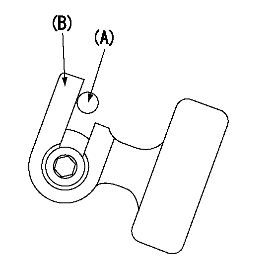
A : Stopper pin
B: Connector
----------
----------
----------
----------
0000001801
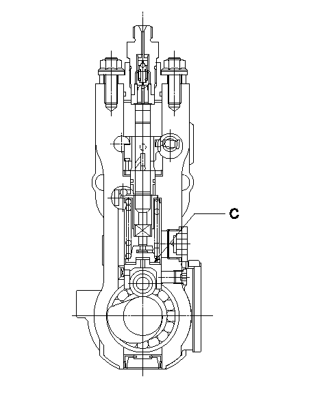
C:Shim
----------
----------
----------
----------
0000001901

A:Sealing position
B:Pre-stroke actuator
1. When installing the pre-stroke actuator on the pump, first tighten the installation bolts loosely, then move the actuator fully counterclockwise (viewed from the drive side).
Temporary tightening torque: 1 - 1.5 N.m (0.1 - 0.15 kgf.m)
2. Move the actuator in the clockwise direction when viewed from the drive side, and adjust so that it becomes the adjustment point of the adjustment value. Then tighten it.
Tightening torque: 7^9 N.m (0.7^0.9 kgf.m)
3. After prestroke actuator installation adjustment, simultaneously stamp both the actuator side and housing side.
----------
----------
----------
----------
0000002201 RACK SENSOR

(VR) measurement voltage
(I) Part number of the control unit
(G) Apply red paint.
(H): End surface of the pump
1. Rack sensor adjustment (-0620)
(1)Fix the speed control lever at the full position
(2)Set the speed to N1 r/min.
(If the boost compensator is provided, apply boost pressure.)
(3)Adjust the bobbin (A) so that the rack sensor's output voltage is VR+-0.01.
(4)At that time, rack position must be Ra.
(5)Apply G at two places.
Connecting part between the joint (B) and the nut (F)
Connecting part between the joint (B) and the end surface of the pump (H)
----------
N1=1400r/min Ra=R1(13.9)+3.15mm
----------
----------
N1=1400r/min Ra=R1(13.9)+3.15mm
----------
0000002301 ACS
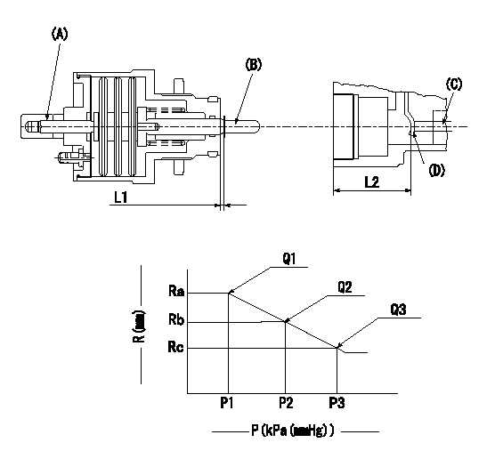
(A) Set screw
(B) Push rod 1
(C) Push rod 2
(D) Lever
1. Aneroid compensator unit adjustment
(1)Screw in (A) to obtain L1.
(2)Select C so that dimension L2 can be obtained.
2. Adjustment when mounting the governor.
(1)Set the speed of the pump to N1 r/min and fix the control lever at the full set position.
(2)Set to full boost.
(3)Screw in the aneroid compensator body to obtain the performance shown in the graph above.
(4)As there is hysterisis, measure when the absolute pressure drops.
(5)Hysterisis must not exceed rack position = h1.
----------
N1=1400r/min L1=1.5+0.5mm L2=37.5+-0.5mm h1=0.15mm
----------
Ra=R3(R1+3.15)mm Rb=(R3-0.25)mm Rc=R3-0.75mm P1=(93.2)kPa((699)mmHg) P2=84.5+-2.7kPa(634+-20mmHg) P3=70.1+-0.7kPa(526+-5mmHg) Q1=(120.5)+-2cm3/1000st Q2=(116.5)cm3/1000st Q3=(112)cm3/1000st
----------
N1=1400r/min L1=1.5+0.5mm L2=37.5+-0.5mm h1=0.15mm
----------
Ra=R3(R1+3.15)mm Rb=(R3-0.25)mm Rc=R3-0.75mm P1=(93.2)kPa((699)mmHg) P2=84.5+-2.7kPa(634+-20mmHg) P3=70.1+-0.7kPa(526+-5mmHg) Q1=(120.5)+-2cm3/1000st Q2=(116.5)cm3/1000st Q3=(112)cm3/1000st
0000002401 POTENTIO METER
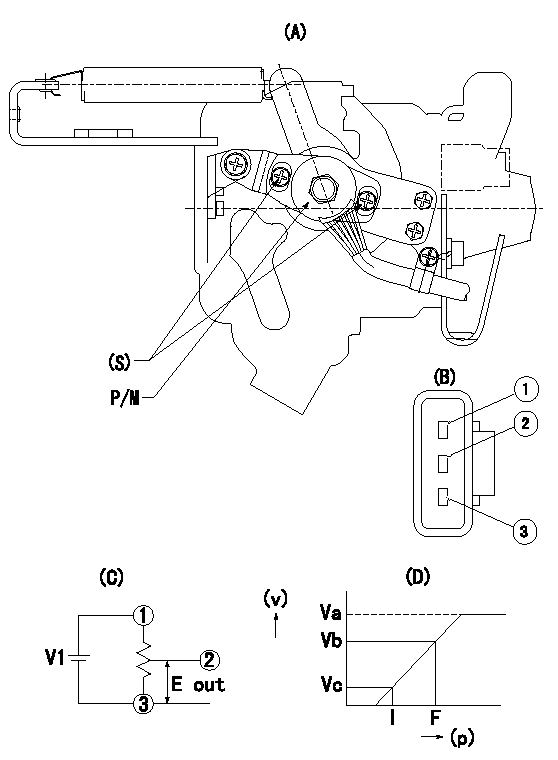
(A) : Governor plan view
(B): Potentiometer harness terminal
(C): Potentiometer connection diagram
(D) : Output voltage standard value
(S): Voltage
P/M: potentiometer
(v): output voltage (V)
(p): direction of potentiometer rotation
1. Adjustment procedures
(1)Apply DCV1 to potentiometer harness terminal (B) to obtain the specified output voltage.
(2)Fix the speed lever at the full side.
(3)Loosen the bolt (S), and move the potentiometer from left and right.
(4)Adjust so that the output voltage at full is within the standard values.
(5)Fix bolt (S).
(6)Repeatedly move the speed lever from the full side to the idle side.
(7)Check that it is within the standard values at full and idle.
----------
V1=5+-0.02V
----------
V1=5+-0.02V Va=(5)V Vb=4+-0.05V Vc=-
----------
V1=5+-0.02V
----------
V1=5+-0.02V Va=(5)V Vb=4+-0.05V Vc=-
Information:
Illustration 31 g00295348
(11) Rotating Group. (15) Shaft.
Install the rotating group (11) .
Position the housing so that the internal end of the shaft (15) is angled downward.
Slide the rotating group (11) over the shaft (15) and into the housing. Ensure that the shoes of the rotating group (11) are seated against the yoke.
Illustration 32 g00295349
(34) Pins
Once the rotating group is installed, turn the rotating group in order to ensure that the three pins (34) are still in the special notches. If the rotating group jams, the pins (34) need to be reinserted into the proper position. The three pins in the rotating group are held in the special notches with a "C" clip retaining ring. The "C" clip applies force against the inside diameter of the rotating group's cylinder block in order to hold the pins in position. See Illustration 32.
Illustration 33 g00295352
(7) Valve Block. (9) Housing Gasket. (35) Large Middle Hole.
Install the housing gasket (9) .
Moderately oil the face of the valve block (7) with clean engine oil. Place the control piston onto the control shaft.
Install the valve block (7) .
Place a finger over the large middle hole (35) in the mounting surface of the valve block (7) in order to create a vacuum. This will hold the control piston in place while you are installing the valve block (7) .
Ensure that the housing gasket (9) is not damaged while you are aligning the valve block (7) to the pins in the pump housing.
Illustration 34 g00295353
(7) Valve Block. (8) Bolts.
Start the bolts (8) in the valve block (7) by hand.
Torque the bolts (8) by alternating from all four sides. Torque the bolts (8) in the corners first. Tighten the bolts (8) to a torque of 27 2 N m (20 1 lb ft).
Illustration 35 g00295295
(5) O-Ring Seals. (6) O-Ring Seals.
Install the four O-Ring seals (5) on the bottom side of the adapter.
Install the four O-Ring seals (6) on the two housings.
Illustration 36 g00295294
(3) Compensator. (4) Bolts.
Install the compensator (3) and the adapter as a unit vertically so that the O-Ring seals are not damaged. Tighten the bolts (4) to a torque of 7.45 .65 N m (65.94 5.75 lb in).
Moderately oil the shaft seal.
Illustration 37 g00295354
(25) Shaft Seal. (36) FT-2608 Bearing Installation Tool .Note: Step 20 through Step 22 defines the procedure for the installation of the shaft seal. These steps should be followed precisely. The shaft seal should be placed barely below the face of the housing. The snap ring should then be positioned against the seal. Both the snap ring and the seal should be driven into the bore together until the snap ring seats in the groove.
Use the FT-2608 Bearing Installation Tool (36) to lower the shaft seal (25) below the edge of the bore.
Place the snap ring against the shaft seal below the edge of the bore.
Illustration 38 g00295356
(25) Shaft Seal. (26) Snap Ring. (36) FT-2608 Bearing Installation Tool .
Use the FT-2608 Bearing Installation Tool (36) in order to lower the shaft seal (25)