Information injection-pump assembly
ZEXEL
107491-3200
1074913200
HINO
220402411A
220402411a

Rating:
Cross reference number
ZEXEL
107491-3200
1074913200
HINO
220402411A
220402411a
Zexel num
Bosch num
Firm num
Name
Calibration Data:
Adjustment conditions
Test oil
1404 Test oil ISO4113 or {SAEJ967d}
1404 Test oil ISO4113 or {SAEJ967d}
Test oil temperature
degC
40
40
45
Nozzle and nozzle holder
105780-8250
Bosch type code
1 688 901 101
Nozzle
105780-0120
Bosch type code
1 688 901 990
Nozzle holder
105780-2190
Opening pressure
MPa
20.7
Opening pressure
kgf/cm2
211
Injection pipe
Outer diameter - inner diameter - length (mm) mm 8-3-600
Outer diameter - inner diameter - length (mm) mm 8-3-600
Overflow valve
131425-0920
Overflow valve opening pressure
kPa
255
221
289
Overflow valve opening pressure
kgf/cm2
2.6
2.25
2.95
Tester oil delivery pressure
kPa
255
255
255
Tester oil delivery pressure
kgf/cm2
2.6
2.6
2.6
PS/ACT control unit part no.
407980-2
24*
Digi switch no.
17
Direction of rotation (viewed from drive side)
Left L
Left L
Injection timing adjustment
Direction of rotation (viewed from drive side)
Left L
Left L
Injection order
1-3-4-2
Pre-stroke
mm
5.1
5.07
5.13
Beginning of injection position
Governor side NO.1
Governor side NO.1
Difference between angles 1
Cal 1-3 deg. 90 89.75 90.25
Cal 1-3 deg. 90 89.75 90.25
Difference between angles 2
Cal 1-4 deg. 180 179.75 180.25
Cal 1-4 deg. 180 179.75 180.25
Difference between angles 3
Cyl.1-2 deg. 270 269.75 270.25
Cyl.1-2 deg. 270 269.75 270.25
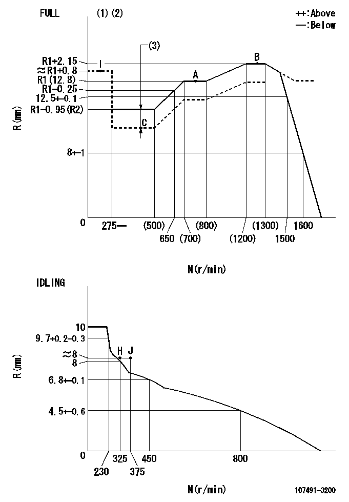
Injection quantity adjustment
Adjusting point
-
Rack position
12.8
Pump speed
r/min
750
750
750
Average injection quantity
mm3/st.
118
115
121
Max. variation between cylinders
%
0
-3.5
3.5
Basic
*
Fixing the rack
*
PS407980-224*
V
2.25+-0.
01
PS407980-224*
mm
3.1+-0.0
5
Standard for adjustment of the maximum variation between cylinders
*
Injection quantity adjustment_02
Adjusting point
Z
Rack position
8+-0.5
Pump speed
r/min
505
505
505
Each cylinder's injection qty
mm3/st.
11.5
10.35
12.65
Fixing the rack
*
PS407980-224*
V
V1+0.05+
-0.01
PS407980-224*
mm
5+-0.03
Standard for adjustment of the maximum variation between cylinders
*
Remarks
Refer to items regarding the pre-stroke actuator
Refer to items regarding the pre-stroke actuator
Injection quantity adjustment_03
Adjusting point
A
Rack position
R1(12.8)
Pump speed
r/min
750
750
750
Average injection quantity
mm3/st.
118
116
120
Basic
*
Fixing the lever
*
Boost pressure
kPa
50.7
50.7
Boost pressure
mmHg
380
380
PS407980-224*
V
2.25+-0.
01
PS407980-224*
mm
3.1+-0.0
5
Injection quantity adjustment_04
Adjusting point
B
Rack position
R1+2.15
Pump speed
r/min
1250
1250
1250
Average injection quantity
mm3/st.
130
124
136
Fixing the lever
*
Boost pressure
kPa
50.7
50.7
Boost pressure
mmHg
380
380
PS407980-224*
V
2.25+-0.
01
PS407980-224*
mm
3.1+-0.0
5
Boost compensator adjustment
Pump speed
r/min
400
400
400
Rack position
R2-1.95
Boost pressure
kPa
12
10.7
13.3
Boost pressure
mmHg
90
80
100
Boost compensator adjustment_02
Pump speed
r/min
400
400
400
Rack position
R2(R1-0.
95)
Boost pressure
kPa
37.3
37.3
37.3
Boost pressure
mmHg
280
280
280
Timer adjustment
Pump speed
r/min
1170--
Advance angle
deg.
0
0
0
Remarks
Start
Start
Timer adjustment_02
Pump speed
r/min
1120
Advance angle
deg.
0
0
0
Remarks
Pointer stamping position
Pointer stamping position
Timer adjustment_03
Pump speed
r/min
1120
Advance angle
deg.
0
-0.3
0
Timer adjustment_04
Pump speed
r/min
1250-50
Advance angle
deg.
-1.5
-1.8
-1.2
Remarks
Finish
Finish
0000001601
CU407980-224*
*
Actuator retarding type
*
Supply voltage
V
24
23.5
24.5
Ambient temperature
degC
23
18
28
Pre-stroke
mm
2
1.95
2.05
Output voltage
V
2.83
2.82
2.84
Adjustment
*
_02
CU407980-224*
*
Supply voltage
V
24
23.5
24.5
Ambient temperature
degC
23
18
28
Pre-stroke
mm
5.1
5.07
5.13
Output voltage
V
1.2
1
1.4
Confirmation
*
Remarks
Output voltage V1
Output voltage V1
_03
CU407980-224*
*
Supply voltage
V
24
23.5
24.5
Ambient temperature
degC
23
18
28
Output voltage
V
3.05
3.05
Confirmation of operating range
*
Test data Ex:
Governor adjustment
N:Pump speed
R:Rack position (mm)
(1)Torque cam stamping: T1
(2)Tolerance for racks not indicated: +-0.05mm.
(3)Boost compensator stroke: BCL
----------
T1=AH35 BCL=1.95+-0.1mm
----------
----------
T1=AH35 BCL=1.95+-0.1mm
----------
Speed control lever angle

F:Full speed
I:Idle
(1)Use the hole at R = aa
(2)Stopper bolt set position 'H'
----------
aa=40mm
----------
a=5deg+-5deg b=34.5deg+-3deg
----------
aa=40mm
----------
a=5deg+-5deg b=34.5deg+-3deg
Stop lever angle
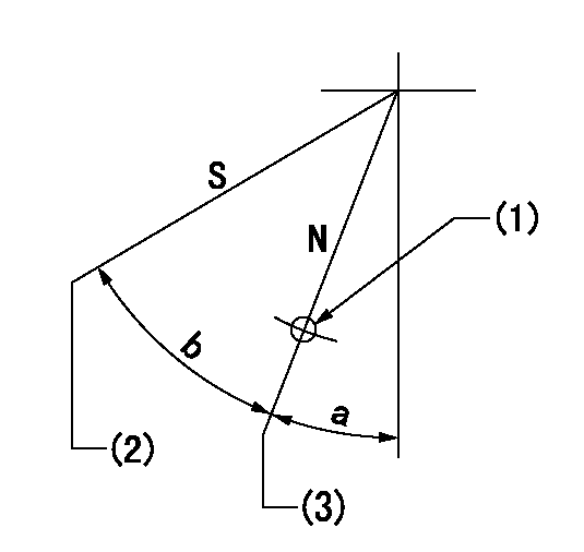
N:Pump normal
S:Stop the pump.
(1)Use the hole at R = aa
(2)At pump speed bb and rack position cc, set the stopper bolt.
(3)Position at the normal side lever position (back off the stop screw and move fully to the normal side). Next, screw in the stop screw and set where it contacts the stop lever.
----------
aa=35mm bb=0r/min cc=3.5+-0.1mm
----------
a=10.5deg+-5deg b=40deg+-5deg
----------
aa=35mm bb=0r/min cc=3.5+-0.1mm
----------
a=10.5deg+-5deg b=40deg+-5deg
0000001301

(1)Pump vertical direction
(2)Coupling's key groove position at No 1 cylinder's beginning of injection
(3)Pre-stroke: aa
(4)-
----------
aa=5.1+-0.03mm
----------
a=(30deg)
----------
aa=5.1+-0.03mm
----------
a=(30deg)
0000001401

(1)Pointer
(2)Injection timing aligning mark
(3)Fly weight
(4)The actual shape and direction may be different from this illustration.
Operation sequence
1. Turn the prestroke actuator OFF.
2. Turn the camshaft as far as the No.1 cylinder's beginning of injection position.
3. Check that the pointer alignment mark of the injection pump and the alignment mark of the flywheel are matching.
4. If they are not matching, erase the alignment mark on the flywheel side, and stamp an alignment mark on the flywheel position that matches with the pointer side alignment mark.
5. Check again that the coupling's key groove position is in the No.1 cylinder's beginning of injection position.
----------
----------
----------
----------
0000001701

A : Stopper pin
B: Connector
----------
----------
----------
----------
0000001801

C:Shim
----------
----------
----------
----------
0000001901

A:Sealing position
B:Pre-stroke actuator
1. When installing the pre-stroke actuator on the pump, first tighten the installation bolts loosely, then move the actuator fully clockwise (viewed from the drive side).
Temporary tightening torque: 1 - 1.5 N.m (0.1 - 0.15 kgf.m)
2. Move the actuator in the counterclockwise direction when viewed from the drive side, and adjust so that it becomes the adjustment point of the adjustment value. Then tighten it.
Tightening torque: 7^9 N.m (0.7^0.9 kgf.m)
3. After prestroke actuator installation adjustment, simultaneously stamp both the actuator side and housing side.
----------
----------
----------
----------
0000002201 RACK SENSOR
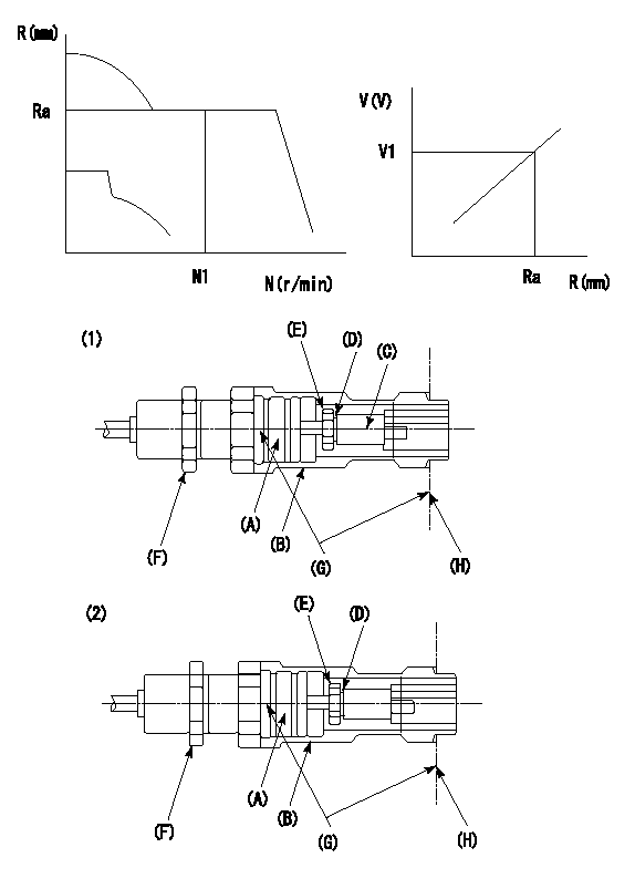
G:Red paint
H:Pump end face
P/N: part number of suitable shim
(1)Threaded type rack block
(2)Welded type rack block
Rack sensor adjustment
1. Threaded type rack sensor (-5*20, P type, no TICS rack limit).
(1)Screw in the bobbin (A) until it contacts the joint (B).
(2)Fix the pump lever.
(3)At speed N1 and rack position Ra, adjust the amount that the bobbin is screwed in so that the amp's output voltage is V1.
(4)Fix using the nut (F).
(5)Affix the caution plate to the upper part of the joint (B).
(6)Apply (G) at two places.
Connecting part between the joint (B) and the nut (F)
Connecting part between the end surface of the pump (H) and the joint (B)
2. Range for screw-in adjustment between the bobbin (A) and the joint (B) is 9 threads.
Screw in to the end from (the position where the bobbin (A) is rotated 9 turns).
Speed N1, rack position Ra, output voltage V1, rack sensor supply voltage 5+-0.01 (V)
----------
Ra=R1(12.8)+2.15mm N1=1250r/min V1=3+-0.01V
----------
----------
Ra=R1(12.8)+2.15mm N1=1250r/min V1=3+-0.01V
----------
Information:
When using Cat ELC, do not use conventional SCAs, or, if equipped, SCA maintenance elements. In order to avoid SCA contamination of an ELC system, remove the SCA element base and plug off or bypass the coolant lines.
Cat ELC Cooling System Cleaning
Note: If the cooling system is already using Cat ELC, cleaning agents are not required at the specified coolant change interval. Cleaning agents are only required if the system has been contaminated by the addition of some other type of coolant or by cooling system damage.Clean water is the only cleaning agent that is required when Cat ELC is drained from a properly maintained cooling system.After the cooling system is drained and after the cooling system is refilled, operate the engine while the cooling system filler cap is removed. Operate the engine until the coolant level reaches the normal operating temperature and until the coolant level stabilizes. As needed, add the coolant mixture in order to fill the system to the proper level.Recycling Cat ELC
Cat ELC can be recycled into conventional coolants. The drained coolant mixture can be distilled in order to remove the ethylene glycol and the water. The ethylene glycol and the water can be reused. The distilled material does not contain the additives that are classified as either Cat ELC or Cat DEAC. Consult your Cat dealer for more information. Recycled coolants should meet the most current revision level of "ASTM D6210".Changing to Cat ELC
To change from heavy-duty coolant/antifreeze to the Cat ELC, perform the following steps:
Care must be taken to ensure that fluids are contained during performance of inspection, maintenance, testing, adjusting and repair of the product. Be prepared to collect the fluid with suitable containers before opening any compartment or disassembling any component containing fluids.Refer to Special Publication, NENG2500, "Caterpillar Dealer Service Tool Catalog" and to Special Publication, PECJ0003, "Cat Shop Supplies and Tools" for tools and supplies suitable to collect and contain fluids on Cat products.Dispose of all fluids according to applicable regulations and mandates.
Drain the coolant into a suitable container.
Dispose of the coolant according to local regulations.
If equipped, remove the empty SCA maintenance element and remove the element base. Plug the coolant lines or bypass the coolant lines.
Do not leave an empty SCA maintenance element on a system that is filled with Cat ELC.The element housing may corrode and leak causing an engine failure.Remove the SCA element base and plug off or by-pass the coolant lines.
Flush the system with clean water in order to remove any debris.
Use Cat Quick Flush Cooling System Cleaner for cooling systems in order to clean the system. Cat Quick Flush Cooling System Cleaner is available in various sizes. Part numbers are 4C-4609 ( 0.5 L (0.125 US gal)) through 4C-4613 ( 208.2 L (55 US gal)). Follow the instructions on the label using a 6-10% concentration of cleaner in water.
Drain the cleaner into a suitable container. Flush the cooling system with clean water. Note: Deposits that remain in the system may be loosened and removed