Information injection-pump assembly
BOSCH
F 01G 09U 0CW
f01g09u0cw
ZEXEL
106991-3002
1069913002
HINO
220008022A
220008022a

Rating:
Service parts 106991-3002 INJECTION-PUMP ASSEMBLY:
1.
_
7.
COUPLING PLATE
8.
_
9.
_
11.
Nozzle and Holder
23600-2480E
12.
Open Pre:MPa(Kqf/cm2)
14.7{150}/24.5{250}
14.
NOZZLE
Include in #1:
106991-3002
as INJECTION-PUMP ASSEMBLY
Cross reference number
BOSCH
F 01G 09U 0CW
f01g09u0cw
ZEXEL
106991-3002
1069913002
HINO
220008022A
220008022a
Zexel num
Bosch num
Firm num
Name
Calibration Data:
Adjustment conditions
Test oil
1404 Test oil ISO4113 or {SAEJ967d}
1404 Test oil ISO4113 or {SAEJ967d}
Test oil temperature
degC
40
40
45
Nozzle and nozzle holder
105780-8140
Bosch type code
EF8511/9A
Nozzle
105780-0000
Bosch type code
DN12SD12T
Nozzle holder
105780-2080
Bosch type code
EF8511/9
Opening pressure
MPa
17.2
Opening pressure
kgf/cm2
175
Injection pipe
Outer diameter - inner diameter - length (mm) mm 8-3-600
Outer diameter - inner diameter - length (mm) mm 8-3-600
Overflow valve
134424-1020
Overflow valve opening pressure
kPa
127
107
147
Overflow valve opening pressure
kgf/cm2
1.3
1.1
1.5
Tester oil delivery pressure
kPa
157
157
157
Tester oil delivery pressure
kgf/cm2
1.6
1.6
1.6
Direction of rotation (viewed from drive side)
Right R
Right R
Injection timing adjustment
Direction of rotation (viewed from drive side)
Right R
Right R
Injection order
1-10-9-4
-3-6-5-8
-7-2
Pre-stroke
mm
4.5
4.44
4.5
Beginning of injection position
Governor side NO.1
Governor side NO.1
Difference between angles 1
Cal 1-10 deg. 27 26.75 27.25
Cal 1-10 deg. 27 26.75 27.25
Difference between angles 2
Cal 1-9 deg. 72 71.75 72.25
Cal 1-9 deg. 72 71.75 72.25
Difference between angles 3
Cal 1-4 deg. 99 98.75 99.25
Cal 1-4 deg. 99 98.75 99.25
Difference between angles 4
Cal 1-3 deg. 144 143.75 144.25
Cal 1-3 deg. 144 143.75 144.25
Difference between angles 5
Cal 1-6 deg. 171 170.75 171.25
Cal 1-6 deg. 171 170.75 171.25
Difference between angles 6
Cal 1-5 deg. 216 215.75 216.25
Cal 1-5 deg. 216 215.75 216.25
Difference between angles 7
Cal 1-8 deg. 243 242.75 243.25
Cal 1-8 deg. 243 242.75 243.25
Difference between angles 8
Cal 1-7 deg. 288 287.75 288.25
Cal 1-7 deg. 288 287.75 288.25
Difference between angles 9
Cyl.1-2 deg. 315 314.75 315.25
Cyl.1-2 deg. 315 314.75 315.25
Injection quantity adjustment
Adjusting point
A
Rack position
9.3
Pump speed
r/min
700
700
700
Average injection quantity
mm3/st.
152
150
154
Max. variation between cylinders
%
0
-2
2
Basic
*
Fixing the lever
*
Injection quantity adjustment_02
Adjusting point
B
Rack position
9.1
Pump speed
r/min
500
500
500
Average injection quantity
mm3/st.
146
143
149
Fixing the lever
*
Injection quantity adjustment_03
Adjusting point
C
Rack position
9.3+-0.5
Pump speed
r/min
1100
1100
1100
Average injection quantity
mm3/st.
141.5
138.5
144.5
Fixing the lever
*
Injection quantity adjustment_04
Adjusting point
D
Rack position
8.6
Pump speed
r/min
1200
1200
1200
Average injection quantity
mm3/st.
124
121
127
Fixing the lever
*
Injection quantity adjustment_05
Adjusting point
E
Rack position
4.3+-0.5
Pump speed
r/min
225
225
225
Average injection quantity
mm3/st.
13
10
16
Max. variation between cylinders
%
0
-15
15
Fixing the rack
*
Injection quantity adjustment_06
Adjusting point
F
Rack position
9.75+-0.
1
Pump speed
r/min
350
350
350
Average injection quantity
mm3/st.
166.5
163.5
169.5
Fixing the lever
*
Remarks
Startup boost setting
Startup boost setting
Injection quantity adjustment_07
Adjusting point
G
Rack position
-
Pump speed
r/min
100
100
100
Average injection quantity
mm3/st.
180
180
190
Fixing the lever
*
Remarks
After startup boost setting
After startup boost setting
Timer adjustment
Pump speed
r/min
450--
Advance angle
deg.
0
0
0
Load
1/4
Remarks
Start
Start
Timer adjustment_02
Pump speed
r/min
400
Advance angle
deg.
0.3
Load
1/4
Timer adjustment_03
Pump speed
r/min
620
Advance angle
deg.
1.5
1.2
1.8
Load
4/4
Timer adjustment_04
Pump speed
r/min
900+50
Advance angle
deg.
1.5
1.2
1.8
Load
3/4
Timer adjustment_05
Pump speed
r/min
1100-50
Advance angle
deg.
5.75
5.45
6.05
Load
4/4
Remarks
Finish
Finish
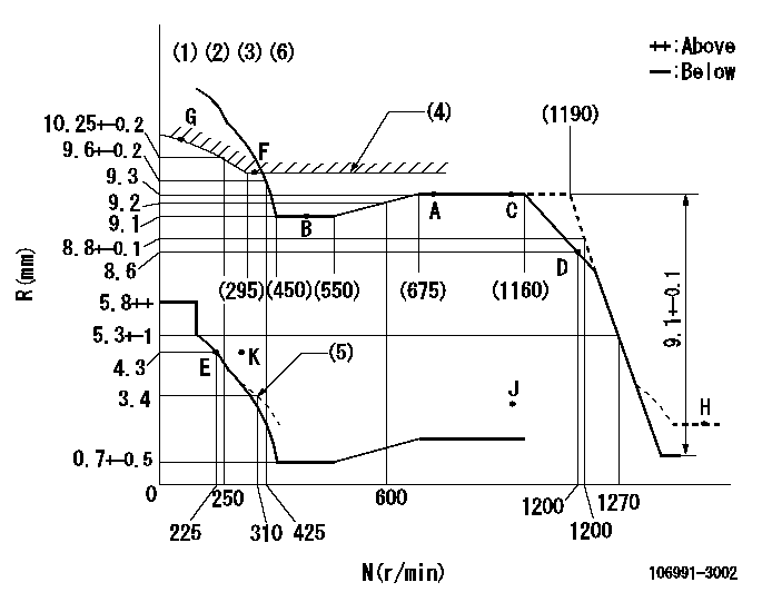
Test data Ex:
Governor adjustment

N:Pump speed
R:Rack position (mm)
(1)Lever ratio: RT
(2)Target shim dimension: TH
(3)Tolerance for racks not indicated: +-0.05mm.
(4)Excess fuel setting for starting: SXL
(5)Damper spring setting
(6)Set idle at point K (N = N1, R = R1) and confirm that the injection quantity does not exceed Q1 at point J (N = N2).
----------
RT=1 TH=2.5mm SXL=9.75+-0.1mm N1=300r/min R1=4.3mm N2=1100r/min Q1=3mm/st
----------
----------
RT=1 TH=2.5mm SXL=9.75+-0.1mm N1=300r/min R1=4.3mm N2=1100r/min Q1=3mm/st
----------
Speed control lever angle

F:Full speed
----------
----------
a=20.5deg+-5deg
----------
----------
a=20.5deg+-5deg
0000000901

F:Full load
I:Idle
(1)Use the hole to the left of R = aa
(2)Stopper bolt setting
----------
aa=56mm
----------
a=30.5deg+-3deg b=23deg+-5deg
----------
aa=56mm
----------
a=30.5deg+-3deg b=23deg+-5deg
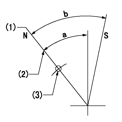
Stop lever angle

N:Pump normal
S:Stop the pump.
(1)Rack position = aa; set before governor adjustment.
(2)Set the stopper bolt (apply red paint).
(3)Use the hole at R = bb
----------
aa=16.5+-0.5mm bb=25mm
----------
a=40deg+-5deg b=50deg+-5deg
----------
aa=16.5+-0.5mm bb=25mm
----------
a=40deg+-5deg b=50deg+-5deg
Timing setting

(1)Pump vertical direction
(2)Coupling's key groove position at No 1 cylinder's beginning of injection
(3)-
(4)-
----------
----------
a=(80deg)
----------
----------
a=(80deg)
Information:
1. Disconnect air line (1) from the fuel ratio control.2. Remove wire seal (4) from the bolts.3. Remove bolts (3) that hold fuel ratio control (2).4. Remove the fuel ratio control by pulling down and out from the collar. The following steps are for the installation of the fuel ratio control.5. Put fuel ratio control (2) in position on the governor. Make sure the valve head of the fuel ratio control is connected in the groove of the collar.6. Install bolts (3) that hold the fuel ratio control to the governor. Connect air line (1) to the fuel ratio control.7. To make an adjustment to the fuel ratio control, see the topic "Governor Adjustment For The Air Fuel Ratio Control" in, Testing & Adjusting Manual SENR6471.8. Install wire seal (4) on the bolts with Tool (A).Disassemble & Assemble Fuel Ratio Control
Start By:a. remove fuel ratio control 1. Put Tool (A) in a vise so that the station being used is not over the vise jaw. Place the fuel ratio control over the pins in Tool (A). Remove bolts (3) and remove cover (26) and gasket (24).
There is spring force behind cover (7). Hold cover (7) in position, and slowly remove the bolts that hold it to release the spring force.
2. Remove bolts (6). Remove cover (7) from housing (10).3. Remove nut (5) and stop (4) from cover (7).4. Remove spring (8), washer (9) and diaphragm (21) from retainer (25). Remove retainer (25) from housing (10).5. Remove tube (1) from the end of extension (19). Remove nut (2) from extension (19) and remove the extension from retainer (25). Remove valve (16), spring (22) and O-ring seal (23) from the extension.6. Remove spring (20), retainer (18) and spring (17) from housing (10).7. Remove piston (12) and valve assembly (14) from the housing.8. Use Tool (B) and remove snap ring (13) and washer (15) from the valve assembly. Remove piston (12) from the valve assembly.9. Remove seal (11) from piston (12).10. If necessary, remove the stem portion from valve assembly (14).11. Clean and inspect all parts. Make a replacement of all parts that are worn and damaged. The following steps are for the assembly of the fuel ratio control.12. If removed during disassembly, assemble the stem portion of valve assembly (14) on the valve using 9S3265 Retaining Compound.13. Lubricate seal (11) lightly with the lubricant being sealed. Put seal (11) on piston (12) and put piston (12) on valve assembly (14).14. Put washer (15) in position on the valve assembly and use Tool (B) to install snap ring (13) on the valve assembly.15. Place housing (10) on Tool (A), and put Tool (C) into the bore of the housing. Lubricate Tool (C) with clean engine oil.16. Push piston (12) into position with a smooth swift motion. Remove Tool (C) from the housing. Place spring (17), retainer (18) and spring (20) in housing (10).17. Put O-ring seal (23) on extension (19). Put spring (22) and valve (16) in position on the