Information injection-pump assembly
ZEXEL
106991-1350
1069911350
ISUZU
1156027510
1156027510
Rating:
Service parts 106991-1350 INJECTION-PUMP ASSEMBLY:
1.
_
6.
COUPLING PLATE
7.
COUPLING PLATE
8.
_
9.
_
11.
Nozzle and Holder
1-15300-204-1
12.
Open Pre:MPa(Kqf/cm2)
15.7{160}/22.1{225}

15.
NOZZLE SET
Include in #1:
106991-1350
as INJECTION-PUMP ASSEMBLY
Cross reference number
ZEXEL
106991-1350
1069911350
ISUZU
1156027510
1156027510
Zexel num
Bosch num
Firm num
Name
Calibration Data:
Adjustment conditions
Test oil
1404 Test oil ISO4113 or {SAEJ967d}
1404 Test oil ISO4113 or {SAEJ967d}
Test oil temperature
degC
40
40
45
Nozzle and nozzle holder
105780-8140
Bosch type code
EF8511/9A
Nozzle
105780-0000
Bosch type code
DN12SD12T
Nozzle holder
105780-2080
Bosch type code
EF8511/9
Opening pressure
MPa
17.2
Opening pressure
kgf/cm2
175
Injection pipe
Outer diameter - inner diameter - length (mm) mm 8-3-600
Outer diameter - inner diameter - length (mm) mm 8-3-600
Overflow valve (drive side)
134424-4320
Overflow valve opening pressure (drive side)
kPa
255
221
289
Overflow valve opening pressure (drive side)
kgf/cm2
2.6
2.25
2.95
Overflow valve (governor side)
134424-4320
Overflow valve opening pressure (governor side)
kPa
255
221
289
Overflow valve opening pressure (governor side)
kgf/cm2
2.6
2.25
2.95
Tester oil delivery pressure
kPa
157
157
157
Tester oil delivery pressure
kgf/cm2
1.6
1.6
1.6
Direction of rotation (viewed from drive side)
Right R
Right R
Injection timing adjustment
Direction of rotation (viewed from drive side)
Right R
Right R
Injection order
1-4-9-8-
5-2-11-1
0-3-6-7-
Pre-stroke
mm
4.2
4.17
4.23
Rack position
Point A R=A
Point A R=A
Beginning of injection position
Governor side NO.1
Governor side NO.1
Difference between angles 1
Cal 1-4 deg. 15 14.75 15.25
Cal 1-4 deg. 15 14.75 15.25
Difference between angles 2
Cal 1-9 deg. 60 59.75 60.25
Cal 1-9 deg. 60 59.75 60.25
Difference between angles 3
Cal 1-8 deg. 75 74.75 75.25
Cal 1-8 deg. 75 74.75 75.25
Difference between angles 4
Cal 1-5 deg. 120 119.75 120.25
Cal 1-5 deg. 120 119.75 120.25
Difference between angles 5
Cyl.1-2 deg. 135 134.75 135.25
Cyl.1-2 deg. 135 134.75 135.25
Difference between angles 6
Cal 1-11 deg. 180 179.75 180.25
Cal 1-11 deg. 180 179.75 180.25
Difference between angles 7
Cal 1-10 deg. 195 194.75 195.25
Cal 1-10 deg. 195 194.75 195.25
Difference between angles 8
Cal 1-3 deg. 240 239.75 240.25
Cal 1-3 deg. 240 239.75 240.25
Difference between angles 9
Cal 1-6 deg. 255 254.75 255.25
Cal 1-6 deg. 255 254.75 255.25
Difference between angles 10
Cal 1-7 deg. 300 299.75 300.25
Cal 1-7 deg. 300 299.75 300.25
Difference between angles 11
Cal 1-12 deg. 315 314.75 315.25
Cal 1-12 deg. 315 314.75 315.25
Injection quantity adjustment
Adjusting point
A
Rack position
8.9
Pump speed
r/min
800
800
800
Average injection quantity
mm3/st.
112
110.5
113.5
Max. variation between cylinders
%
0
-2
2
Basic
*
Fixing the lever
*
Injection quantity adjustment_02
Adjusting point
C
Rack position
8.5
Pump speed
r/min
1150
1150
1150
Average injection quantity
mm3/st.
124.9
122.9
126.9
Fixing the lever
*
Injection quantity adjustment_03
Adjusting point
D
Rack position
4.9+-0.5
Pump speed
r/min
225
225
225
Average injection quantity
mm3/st.
8.8
7.5
10.1
Max. variation between cylinders
%
0
-13
13
Fixing the rack
*
Test data Ex:
Governor adjustment
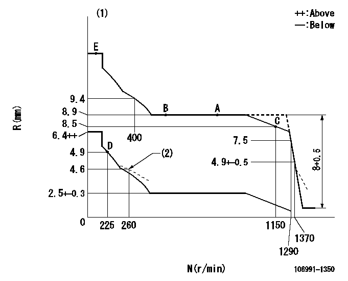
N:Pump speed
R:Rack position (mm)
(1)Tolerance for racks not indicated: +-0.05mm.
(2)Damper spring setting
----------
----------
----------
----------
Timer adjustment

(1)Adjusting range
(2)Step response time
(N): Speed of the pump
(L): Load
(theta) Advance angle
(Srd1) Step response time 1
(Srd2) Step response time 2
1. Adjusting conditions for the variable timer
(1)Adjust the clearance between the pickup and the protrusion to L.
----------
L=1-0.2mm N2=800r/min C2=(7)deg t1=1.5--sec. t2=1.5--sec.
----------
N1=1100++r/min P1=0kPa(0kgf/cm2) P2=392kPa(4kgf/cm2) C1=7+-0.3deg R01=0/4load R02=4/4load
----------
L=1-0.2mm N2=800r/min C2=(7)deg t1=1.5--sec. t2=1.5--sec.
----------
N1=1100++r/min P1=0kPa(0kgf/cm2) P2=392kPa(4kgf/cm2) C1=7+-0.3deg R01=0/4load R02=4/4load
Speed control lever angle

F:Full speed
----------
----------
a=7deg+-5deg
----------
----------
a=7deg+-5deg
0000000901
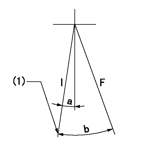
F:Full load
I:Idle
(1)Stopper bolt setting
----------
----------
a=10deg+-5deg b=34.5deg+-3deg
----------
----------
a=10deg+-5deg b=34.5deg+-3deg
Stop lever angle
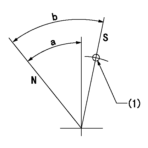
N:Pump normal
S:Stop the pump.
(1)Use the hole at R = aa
----------
aa=25mm
----------
a=51deg+-5deg b=64deg+-5deg
----------
aa=25mm
----------
a=51deg+-5deg b=64deg+-5deg
0000001501 RACK SENSOR
Rack sensor adjustment
(1)These types of rack sensors do not need adjustment. Confirm the output as described below.
(2)Mount the rack sensor main body to the pump main body.
(3)Measure the Vist at pump speed N1 and rack position Ra.
----------
N1=500r/min Ra=8.9mm
----------
----------
N1=500r/min Ra=8.9mm
----------
Timing setting

(1)Pump vertical direction
(2)Position of "Z" mark at the No 1 cylinder's beginning of injection (governor side)
(3)B.T.D.C.: aa (set timing)
(4)-
----------
aa=8deg
----------
a=(180deg)
----------
aa=8deg
----------
a=(180deg)
Information:
Oils
Hot oil and components can cause personal injury. Do not allow hot oil or components to contact the skin.Keep all exhaust manifold and turbocharger shields in place to protect hot exhaust from oil spray in the event of a line, tube or seal failure.Batteries
Battery electrolyte contains acid and can cause injury. Avoid contact with the skin and eyes.Wash hands after touching batteries and connectors. Use of gloves is recommended.Batteries give off flammable fumes which can explode. Ensure there is proper ventilation for batteries which are located in an enclosure.Always thaw a frozen battery before jump starting. Frozen batteries can explode.Do not smoke when observing the battery electrolyte levels.Always wear protective glasses when working with batteries.Never disconnect any charging unit circuit or battery circuit cable from the battery when charging unit is operating. A spark can cause the flammable vapor mixture of hydrogen and oxygen to explode.Fire or Explosion Prevention
Fire may result from lubricating oil or fuel sprayed on hot surfaces causing personal injury and property damage. Inspect all lines and tubes for wear or deterioration. They must be routed, supported or clamped securely. Tighten all connections to the recommended torque. Leaks can cause fires.Determine whether the engine will be operated in an environment in which combustible gases could be drawn through the air inlet system. These gases could cause the engine to overspeed, which in turn could seriously damage the engine and result in bodily injury or property damage.If your application involves the presence of combustible gases, consult your Caterpillar dealer to obtain additional information concerning protection devices (i.e. air inlet shutoff) suitable for the application involved.All fuels, most lubricants and some coolant mixtures are flammable.Diesel fuel is flammable. Gasoline is flammable. The mixture of diesel and gasoline fumes are extremely explosive.Do not smoke while refueling or in a refueling area.Do not smoke in areas where batteries are charged, or where flammable materials are stored.Batteries give off flammable fumes which can explode.Keep all fuels and lubricants stored in properly marked containers and away from all unauthorized persons.Store all oily rags or other flammable material in a protective container, in a safe place.Do not weld or flame cut on pipes or tubes that contain flammable fluids. Clean them thoroughly with nonflammable solvent before welding or flame cutting on them.Remove all flammable materials such as fuel, oil and other debris before they accumulate on the engine.Do not expose the engine to flames, burning brush, etc., if at all possible.Shields (if equipped), which protect hot exhaust components from oil or fuel spray in the event of a line, tube or seal failure, must be installed correctly.Provide adequate and proper waste oil disposal. Oil and fuel filters must be properly installed and housing covers tightened to proper torque when being changed.Batteries must be kept clean, covers kept on all cells, recommended cables and connections used and battery box covers kept in place when operating.When starting from an external source, always connect the positive (+) jumper cable to the POSITIVE (+) terminal of